


ELECTRICAL— BODY AND CHASSIS 12-2
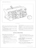
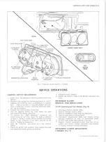
Fig. 1 — Fuse Panel
aiming is even more important because the increased
range and power of this lamp make even slight variations
from recommended aiming hazardous to approaching
motorists.
The headlamps must be checked for proper aim when
ever a sealed beam unit is replaced and after repairs of
the front end sheet metal assembly.
Regardless of the method used for checking headlamp
aim, the truck must be at normal weight, that is with gas,
oil, water and spare tire. Tires must be inflated to the
specified pressures.
Some states have special requirements for headlamp
aiming adjustment and these requirements must be known
and followed.
Horizontal and vertical aiming of each sealed beam is
provided by two adjusting screws visible through the
bezel which move the mounting ring against the tension
of the coil spring.
There is no adjustment for focus since the sealed beam
unit is set for focus during manufacturing assembly.
SERVICE OPERATIONS
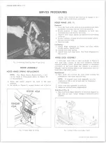
SEALED BEAM UNIT REPLACEMENT (Fig. 3)
1. Remove bezel retaining screws and bezel.
2. Disengage spring from retaining ring.
3. Turn headlamp unit to disen9age assembly from
headlamp adjusting screws.
4. Disconnect wiring harness connector located at rear
of unit in engine compartment.
NOTE:
Do not disturb adjusting screw setting.
5. Remove retaining ring and headlamp from mounting
ring.
6. Position new sealed beam unit in mounting ring and
install retaining ring.
NOTE:
The number molded into lens face must
be at top.
7. Attach wiring harness connector to unit.
8. Install headlamp assembly in panel opening, twisting
slightly to engage mounting ring tabs with adjusting
screws.
9. Install retaining ring spring then check operation of
unit and install bezel.
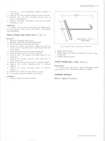
PARKING, CLEARANCE A N D IDENTIFICATION
BULB REPLACEMENT
1. Remove retaining screw(s) and lens from housing.
2. Replace bulb and check operation of unit.
3. Install lens and retaining screws.
PARKING LAMP H OU SIN G REPLACEMENT (Fig. 3)
1. R em ove headlam p bezel on P s e r ie s tru c k s.
10-30 CHEVROLET TRUCK SERVICE MANUAL
Содержание 10 1971 Series
Страница 1: ......
Страница 96: ......
Страница 100: ...10 30 CHEVROLET TRUCK SERVICE MANUAL Fig 4 10 30 Series Truck Frame FRAME 2 4 ...
Страница 120: ......
Страница 203: ...ENGINE 6 25 Fig 22L Engine Mounts 10 30 CHEVROLET TRUCK SERVICE MANUAL ...
Страница 215: ...ENGINE 6 37 REAR M O U NT Fig 21V Engine Mounts 10 30 CHEVROLET TRUCK SERVICE MANUAL ...
Страница 218: ......
Страница 249: ......
Страница 250: ...EMISSION CONTROL SYSTEMS 6T 4 Fig 3 Combination Emission Control System Routing V8 10 30 CHEVROLET TRUCK SERVICE MANUAL ...
Страница 324: ......
Страница 339: ...FUEL TANK AND EXHAUST SYSTEMS 8 15 SPECIAL TOOLS Fig 22 Special Tools 1 J 23346 Fuel Tank Gauge Remover and Installer ...
Страница 340: ......
Страница 365: ...10 30 CHEVROLET TRUCK SERVICE MANUAL Fig 43 Power Steering Pump M ounting STEERING 9 25 ...
Страница 368: ......
Страница 386: ......
Страница 390: ...ELECTRICAL BODY AND CHASSIS 12 4 10 30 CHEVROLET TRUCK SERVICE MANUAL ...
Страница 391: ......
Страница 392: ...ELECTRICAL BODY AND CHASSIS 12 6 Fig 5 Rear Lighting Composite 10 30 CHEVROLET TRUCK SERVICE MANUAL ...
Страница 409: ...ELECTRICAL BODY AND CHASSIS 12 23 Fig 27 Engine Compartment CA30 02 10 30 CHEVROLET TRUCK SERVICE MANUAL ...
Страница 410: ...ELECTRICAL BODY AND CHASSIS 12 24 18DK GRN 19 Fig 28 Instrument Panel CA30 02 10 30 CHEVROLET TRUCK SERVICE MANUAL ...
Страница 411: ...ELECTRICAL BODY AND CHASSIS 12 25 Fig 29 Instrument Panel CA30 02 10 30 CHEVROLET TRUCK SERVICE MANUAL ...
Страница 412: ...ELECTRICAL BODY AND CHASSIS 12 26 fh Ar r kk 4 Fig 30 Engine Compartment C A K A 10 20 CA30 03 z _ ...
Страница 416: ...ELECTRICAL BODY AND CHASSIS 12 30 Fig 34 Engine Compartment CA KA10 20 CA30 04 10 30 CHEVROLET TRUCK SERVICE MANUAL ...
Страница 420: ...ELECTRICAL BODY AND CHASSIS 12 34 Fig 38 Engine Compartment C A K A 1 0 20 06 16 10 30 CHEVROLET TRUCK SERVICE MANUAL ...
Страница 422: ...ELECTRICAL BODY AND CHASSIS 12 36 Fig 40 Instrument Panel C A K A 10 20 06 16 10 30 CHEVROLET TRUCK SERVICE MANUAL ...
Страница 423: ...ELECTRICAL BODY AND CHASSIS 12 37 Fig 41 R ear Lamps C A K A 1 0 20 06 16 10 30 CHEVROLET TRUCK SERVICE MANUAL ...
Страница 424: ...ELECTRICAL BODY AND CHASSIS 12 38 Fig 42 Engine Compartment CA KA10 20 CAl30 14 34 10 30 CHEVROLET TRUCK SERVICE MANUAL ...
Страница 426: ...ELECTRICAL BODY AND CHASSIS 12 40 Fig 44 Instrument Panel CA KA10 20 CA30 14 34 10 30 CHEVROLET TRUCK SERVICE MANUAL ...
Страница 428: ......
Страница 432: ......
Страница 449: ...SPECIFICATIONS 9 10 30 CHEVROLET TRUCK SERVICE MANUAL ...
Страница 463: ......
Страница 464: ......
Страница 465: ......
Страница 466: ......