


STEERING 9-19
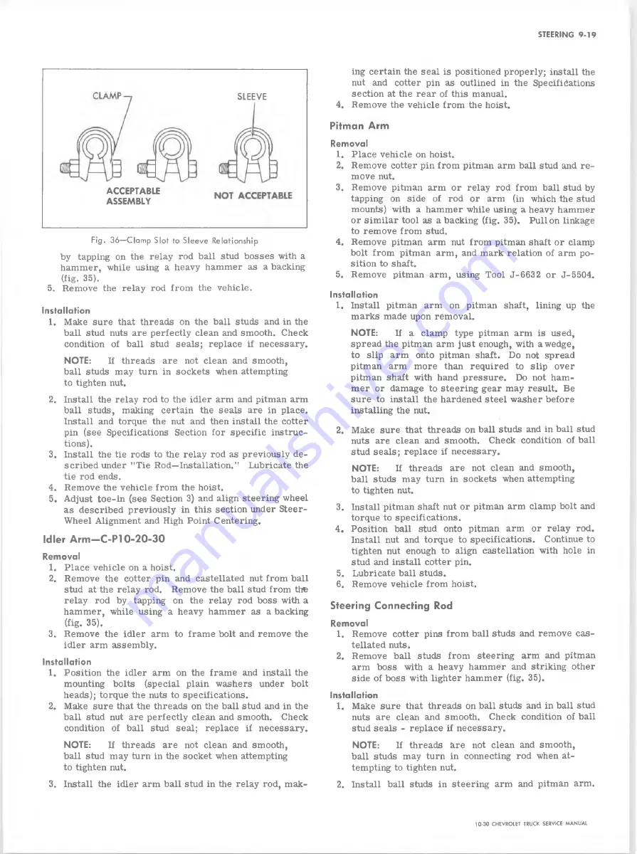
SLEEVE
ACCEPTABLE
ASSEMBLY
Fig. 36— Clamp Slot to Sleeve Relationship
by tapping on the relay rod ball stud bosses with a
hammer, while using a heavy hammer as a backing
(fig. 35).
5. Remove the relay rod from the vehicle.
Installation
1. Make sure that threads on the ball studs and in the
ball stud nuts are perfectly clean and smooth. Check
condition of ball stud seals; replace if necessary.
NOTE:
If threads are not clean and smooth,
ball studs may turn in sockets when attempting
to tighten nut.
2. Install the relay rod to the idler arm and pitman arm
ball studs, making certain the seals are in place.
Install and torque the nut and then install the cotter
pin (see Specifications Section for specific instruc
tions).
3. Install the tie rods to the relay rod as previously de
scribed under ’’Tie Rod—Installation." Lubricate the
tie rod ends.
4. Remove the vehicle from the hoist.
5. Adjust toe-in (see Section 3) and align steering wheel
as described previously in this section under Steer-
Wheel Alignment and High Point Centering.
Idler A r m -C -P l 0-20-30
Removal
1. Place vehicle on a hoist.
2. Remove the cotter pin and castellated nut from ball
stud at the relay rod. Remove the ball stud from the
relay rod by tapping on the relay rod boss with a
hammer, while using a heavy hammer as a backing
(fig. 35).
3. Remove the idler arm to frame bolt and remove the
idler arm assembly.
Installation
1. Position the idler arm on the frame and install the
mounting bolts (special plain washers under bolt
heads); torque the nuts to specifications.
2. Make sure that the threads on the ball stud and in the
ball stud nut are perfectly clean and smooth. Check
condition of ball stud seal; replace if necessary.
NOTE:
If threads are not clean and smooth,
ball stud may turn in the socket when attempting
to tighten nut.
3. Install the idler arm ball stud in the relay rod, mak
ing certain the seal is positioned properly; install the
nut and cotter pin as outlined in the Specifications
section at the rear of this manual.
4. Remove the vehicle from the hoist.
Pitman Arm
Removal
1. Place vehicle on hoist.
2. Remove cotter pin from pitman arm ball stud and re
move nut.
3. Remove pitman arm or relay rod from ball stud by
tapping on side of rod or arm (in which the stud
mounts) with a hammer while using a heavy hammer
or similar tool as a backing (fig. 35). Pull on linkage
to remove from stud.
4. Remove pitman arm nut from pitman shaft or clamp
bolt from pitman arm, and mark relation of arm po
sition to shaft.
5. Remove pitman arm, using Tool J-6632 or J-5504.
Installation
1. Install pitman arm on pitman shaft, lining up the
marks made upon removal.
N O T E :
If a clamp type pitman arm is used,
spread the pitman arm just enough, with a wedge,
to slip arm onto pitman shaft. Do not spread
pitman arm more than required to slip over
pitman shaft with hand pressure. Do not ham
mer or damage to steering gear may result. Be
sure to install the hardened steel washer before
installing the nut.
2. Make sure that threads on ball studs and in ball stud
nuts are clean and smooth. Check condition of ball
stud seals; replace if necessary.
N O T E :
If threads are not clean and smooth,
ball studs may turn in sockets when attempting
to tighten nut.
3. Install pitman shaft nut or pitman arm clamp bolt and
torque to specifications.
4. Position ball stud onto pitman arm or relay rod.
Install nut and torque to specifications. Continue to
tighten nut enough to align castellation with hole in
stud and install cotter pin.
5. Lubricate ball studs.
6. Remove vehicle from hoist.
Steering Connecting Rod
Removal
1. Remove cotter pins from ball studs and remove cas
tellated nuts.
2. Remove ball studs from steering arm and pitman
arm boss with a heavy hammer and striking other
side of boss with lighter hammer (fig. 35).
Installation
1. Make sure that threads on ball studs and in ball stud
nuts are clean and smooth. Check condition of ball
stud seals - replace if necessary.
N O T E :
If threads are not clean and smooth,
ball studs may turn in connecting rod when at
tempting to tighten nut.
2. Install ball studs in steering arm and pitman arm.
10-30 CHEVROLET TRUCK SERVICE MANUAL
Содержание 10 1971 Series
Страница 1: ......
Страница 96: ......
Страница 100: ...10 30 CHEVROLET TRUCK SERVICE MANUAL Fig 4 10 30 Series Truck Frame FRAME 2 4 ...
Страница 120: ......
Страница 203: ...ENGINE 6 25 Fig 22L Engine Mounts 10 30 CHEVROLET TRUCK SERVICE MANUAL ...
Страница 215: ...ENGINE 6 37 REAR M O U NT Fig 21V Engine Mounts 10 30 CHEVROLET TRUCK SERVICE MANUAL ...
Страница 218: ......
Страница 249: ......
Страница 250: ...EMISSION CONTROL SYSTEMS 6T 4 Fig 3 Combination Emission Control System Routing V8 10 30 CHEVROLET TRUCK SERVICE MANUAL ...
Страница 324: ......
Страница 339: ...FUEL TANK AND EXHAUST SYSTEMS 8 15 SPECIAL TOOLS Fig 22 Special Tools 1 J 23346 Fuel Tank Gauge Remover and Installer ...
Страница 340: ......
Страница 365: ...10 30 CHEVROLET TRUCK SERVICE MANUAL Fig 43 Power Steering Pump M ounting STEERING 9 25 ...
Страница 368: ......
Страница 386: ......
Страница 390: ...ELECTRICAL BODY AND CHASSIS 12 4 10 30 CHEVROLET TRUCK SERVICE MANUAL ...
Страница 391: ......
Страница 392: ...ELECTRICAL BODY AND CHASSIS 12 6 Fig 5 Rear Lighting Composite 10 30 CHEVROLET TRUCK SERVICE MANUAL ...
Страница 409: ...ELECTRICAL BODY AND CHASSIS 12 23 Fig 27 Engine Compartment CA30 02 10 30 CHEVROLET TRUCK SERVICE MANUAL ...
Страница 410: ...ELECTRICAL BODY AND CHASSIS 12 24 18DK GRN 19 Fig 28 Instrument Panel CA30 02 10 30 CHEVROLET TRUCK SERVICE MANUAL ...
Страница 411: ...ELECTRICAL BODY AND CHASSIS 12 25 Fig 29 Instrument Panel CA30 02 10 30 CHEVROLET TRUCK SERVICE MANUAL ...
Страница 412: ...ELECTRICAL BODY AND CHASSIS 12 26 fh Ar r kk 4 Fig 30 Engine Compartment C A K A 10 20 CA30 03 z _ ...
Страница 416: ...ELECTRICAL BODY AND CHASSIS 12 30 Fig 34 Engine Compartment CA KA10 20 CA30 04 10 30 CHEVROLET TRUCK SERVICE MANUAL ...
Страница 420: ...ELECTRICAL BODY AND CHASSIS 12 34 Fig 38 Engine Compartment C A K A 1 0 20 06 16 10 30 CHEVROLET TRUCK SERVICE MANUAL ...
Страница 422: ...ELECTRICAL BODY AND CHASSIS 12 36 Fig 40 Instrument Panel C A K A 10 20 06 16 10 30 CHEVROLET TRUCK SERVICE MANUAL ...
Страница 423: ...ELECTRICAL BODY AND CHASSIS 12 37 Fig 41 R ear Lamps C A K A 1 0 20 06 16 10 30 CHEVROLET TRUCK SERVICE MANUAL ...
Страница 424: ...ELECTRICAL BODY AND CHASSIS 12 38 Fig 42 Engine Compartment CA KA10 20 CAl30 14 34 10 30 CHEVROLET TRUCK SERVICE MANUAL ...
Страница 426: ...ELECTRICAL BODY AND CHASSIS 12 40 Fig 44 Instrument Panel CA KA10 20 CA30 14 34 10 30 CHEVROLET TRUCK SERVICE MANUAL ...
Страница 428: ......
Страница 432: ......
Страница 449: ...SPECIFICATIONS 9 10 30 CHEVROLET TRUCK SERVICE MANUAL ...
Страница 463: ......
Страница 464: ......
Страница 465: ......
Страница 466: ......


