


STEERING 9-18
replacement becomes necessary. Do not use
replacement parts of lesser quality or substi
tute design. Torque values must be used as
specified during reassembly to assure proper
retention of these parts.
Tie Rod
Removal
1. Place vehicle on hoist.
2. Remove cotter pins from ball studs and remove castel
lated nuts.
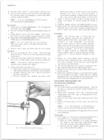
3. To remove outer ball stud, tap on steering arm at
tie rod end with a hammer while using a heavy ham
mer or similar tool as a backing (fig. 35).
4. Remove inner ball stud from relay rod using same
procedure as described in Step 3.
5. To remove tie rod ends from tie rod, loosen clamp
bolts and unscrew end assemblies.
Installation
1. If the tie rod ends were removed, lubricate the tie rod
threads with EP Chassis lube and install ends on tie
rod making sure both ends are threaded an equal
distance from the tie rod.
2. Make sure that threads on ball studs and in ball stud
nuts are perfectly clean and smooth. Check condi
tion of ball stud seals; replace if necessary.
NOTE:
If threads are not clean and smooth,
ball studs may turn in tie rod ends when attempt
ing to tighten nut.
3.
Install ball studs in steering arms and relay rod.
4. Install ball stud nut, tighten and install new cotter
pins; see Specifications Section at rear of manual.
Lubricate tie rod ends.
5. Remove vehicle from hoist.
6.
Adjust toe-in as described in Section
3.
C A U T IO N :
Before tightening the tie rod ad-
justing sleeve clamp bolts, be sure that the fol
lowing conditions have been met:
a. The sleeve clamps must be positioned between
the locating dimples at either end of the sleeve.
b. The clamps must be positioned within the angular
travel indicated in Figure
33.
c. The relationship of the clamp slot with the slit
in the sleeve should be maintained as shown in
Figure
36.
d. Both inner and outer tie rod ends must rotate for
full travel in the same direction. The position of
each tie rod end must be maintained as the clamps
are tightened to ensure free movement of each
joint.
e. All procedures for alignment, adjustment and
assembly of tie rods applies to each side.
Relay R o d - C - P l0-20-30
Removal
1. Place vehicle on hoist.
2. Remove inner ends of the tie rods'from' relay rod as
described under "Tie Rod—Removal."
3.
Remove the cotter pins from the pitman and idler
arm ball studs at the relay rod. Remove the cas
tellated nuts.
4. Remove the relay rod from the pitman and idler arms
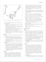
Fig. 34 — K 1 0 -2 0 Series Steering Linkage
Fig. 35— Ball Stud Removal (Typical)
10-30 CHEVROLET TRUCK SERVICE MANUAL
Содержание 10 1971 Series
Страница 1: ......
Страница 96: ......
Страница 100: ...10 30 CHEVROLET TRUCK SERVICE MANUAL Fig 4 10 30 Series Truck Frame FRAME 2 4 ...
Страница 120: ......
Страница 203: ...ENGINE 6 25 Fig 22L Engine Mounts 10 30 CHEVROLET TRUCK SERVICE MANUAL ...
Страница 215: ...ENGINE 6 37 REAR M O U NT Fig 21V Engine Mounts 10 30 CHEVROLET TRUCK SERVICE MANUAL ...
Страница 218: ......
Страница 249: ......
Страница 250: ...EMISSION CONTROL SYSTEMS 6T 4 Fig 3 Combination Emission Control System Routing V8 10 30 CHEVROLET TRUCK SERVICE MANUAL ...
Страница 324: ......
Страница 339: ...FUEL TANK AND EXHAUST SYSTEMS 8 15 SPECIAL TOOLS Fig 22 Special Tools 1 J 23346 Fuel Tank Gauge Remover and Installer ...
Страница 340: ......
Страница 365: ...10 30 CHEVROLET TRUCK SERVICE MANUAL Fig 43 Power Steering Pump M ounting STEERING 9 25 ...
Страница 368: ......
Страница 386: ......
Страница 390: ...ELECTRICAL BODY AND CHASSIS 12 4 10 30 CHEVROLET TRUCK SERVICE MANUAL ...
Страница 391: ......
Страница 392: ...ELECTRICAL BODY AND CHASSIS 12 6 Fig 5 Rear Lighting Composite 10 30 CHEVROLET TRUCK SERVICE MANUAL ...
Страница 409: ...ELECTRICAL BODY AND CHASSIS 12 23 Fig 27 Engine Compartment CA30 02 10 30 CHEVROLET TRUCK SERVICE MANUAL ...
Страница 410: ...ELECTRICAL BODY AND CHASSIS 12 24 18DK GRN 19 Fig 28 Instrument Panel CA30 02 10 30 CHEVROLET TRUCK SERVICE MANUAL ...
Страница 411: ...ELECTRICAL BODY AND CHASSIS 12 25 Fig 29 Instrument Panel CA30 02 10 30 CHEVROLET TRUCK SERVICE MANUAL ...
Страница 412: ...ELECTRICAL BODY AND CHASSIS 12 26 fh Ar r kk 4 Fig 30 Engine Compartment C A K A 10 20 CA30 03 z _ ...
Страница 416: ...ELECTRICAL BODY AND CHASSIS 12 30 Fig 34 Engine Compartment CA KA10 20 CA30 04 10 30 CHEVROLET TRUCK SERVICE MANUAL ...
Страница 420: ...ELECTRICAL BODY AND CHASSIS 12 34 Fig 38 Engine Compartment C A K A 1 0 20 06 16 10 30 CHEVROLET TRUCK SERVICE MANUAL ...
Страница 422: ...ELECTRICAL BODY AND CHASSIS 12 36 Fig 40 Instrument Panel C A K A 10 20 06 16 10 30 CHEVROLET TRUCK SERVICE MANUAL ...
Страница 423: ...ELECTRICAL BODY AND CHASSIS 12 37 Fig 41 R ear Lamps C A K A 1 0 20 06 16 10 30 CHEVROLET TRUCK SERVICE MANUAL ...
Страница 424: ...ELECTRICAL BODY AND CHASSIS 12 38 Fig 42 Engine Compartment CA KA10 20 CAl30 14 34 10 30 CHEVROLET TRUCK SERVICE MANUAL ...
Страница 426: ...ELECTRICAL BODY AND CHASSIS 12 40 Fig 44 Instrument Panel CA KA10 20 CA30 14 34 10 30 CHEVROLET TRUCK SERVICE MANUAL ...
Страница 428: ......
Страница 432: ......
Страница 449: ...SPECIFICATIONS 9 10 30 CHEVROLET TRUCK SERVICE MANUAL ...
Страница 463: ......
Страница 464: ......
Страница 465: ......
Страница 466: ......