


STEERING 9-10
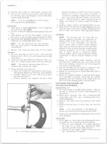
5. Bend the wire retaining tabs slightly outward on
each wire in the wiring harness as shown in Figure
17; this will provide proper retention of the wire in
the half-moon connector.
6. Install each wire in its marked location in the half
moon connector. Push in until square part of clip
is flush with the bottom side of the connector. Con
nect the directional signal switch wiring harness.
7. Snap the wiring harness protector into the column
retaining slots.
8. Install the directional signal cancelling cam and
spring.
9. Install the steering wheel as outlined under "Steer
ing Wheel - Installation".
10. Install the column to instrument panel trim plate (if
so equipped).
STEERING COLUMN
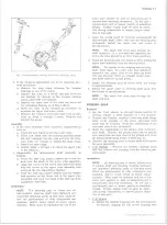
Removal (Fig. 18)
1. Disconnect the battery ground cable.
2. Column Shift Models - Disconnect transmission
shifter rods at the lower end of the column.
3. C-K Models - Remove the intermediate steering shaft
flange to flexible coupling bolts.
P Models - Remove the intermediate steering shaft
upper universal yoke to steering shaft pinch bolt.
Mark the coupling to shaft relationship.
4. Remove column clamp screw(s) on engine side of
firewall and remove or slide the clamp down the
column.
5. From inside the vehicle, remove the screws from the
BEND TABS O U T W A R D
EACH SIDE
Fig. 17— Preparing Wire Retaining Tabs for Installation
3.
Tilt Columns Only—
a. Align the openings in the directional signal switch
cover with the proper lever positions and tap the
cover into place using a plastic hammer.
b. Install the tilt release lever.
c. Automatic Transmission Models - Install the
PRNDL dial, pointer, dial illumination bulb and
cap.
4. Install the directional signal switch lever and hazard
warning knob.
10-30 CHEVROLET TRUCK SERVICE MANUAL
Содержание 10 1971 Series
Страница 1: ......
Страница 96: ......
Страница 100: ...10 30 CHEVROLET TRUCK SERVICE MANUAL Fig 4 10 30 Series Truck Frame FRAME 2 4 ...
Страница 120: ......
Страница 203: ...ENGINE 6 25 Fig 22L Engine Mounts 10 30 CHEVROLET TRUCK SERVICE MANUAL ...
Страница 215: ...ENGINE 6 37 REAR M O U NT Fig 21V Engine Mounts 10 30 CHEVROLET TRUCK SERVICE MANUAL ...
Страница 218: ......
Страница 249: ......
Страница 250: ...EMISSION CONTROL SYSTEMS 6T 4 Fig 3 Combination Emission Control System Routing V8 10 30 CHEVROLET TRUCK SERVICE MANUAL ...
Страница 324: ......
Страница 339: ...FUEL TANK AND EXHAUST SYSTEMS 8 15 SPECIAL TOOLS Fig 22 Special Tools 1 J 23346 Fuel Tank Gauge Remover and Installer ...
Страница 340: ......
Страница 365: ...10 30 CHEVROLET TRUCK SERVICE MANUAL Fig 43 Power Steering Pump M ounting STEERING 9 25 ...
Страница 368: ......
Страница 386: ......
Страница 390: ...ELECTRICAL BODY AND CHASSIS 12 4 10 30 CHEVROLET TRUCK SERVICE MANUAL ...
Страница 391: ......
Страница 392: ...ELECTRICAL BODY AND CHASSIS 12 6 Fig 5 Rear Lighting Composite 10 30 CHEVROLET TRUCK SERVICE MANUAL ...
Страница 409: ...ELECTRICAL BODY AND CHASSIS 12 23 Fig 27 Engine Compartment CA30 02 10 30 CHEVROLET TRUCK SERVICE MANUAL ...
Страница 410: ...ELECTRICAL BODY AND CHASSIS 12 24 18DK GRN 19 Fig 28 Instrument Panel CA30 02 10 30 CHEVROLET TRUCK SERVICE MANUAL ...
Страница 411: ...ELECTRICAL BODY AND CHASSIS 12 25 Fig 29 Instrument Panel CA30 02 10 30 CHEVROLET TRUCK SERVICE MANUAL ...
Страница 412: ...ELECTRICAL BODY AND CHASSIS 12 26 fh Ar r kk 4 Fig 30 Engine Compartment C A K A 10 20 CA30 03 z _ ...
Страница 416: ...ELECTRICAL BODY AND CHASSIS 12 30 Fig 34 Engine Compartment CA KA10 20 CA30 04 10 30 CHEVROLET TRUCK SERVICE MANUAL ...
Страница 420: ...ELECTRICAL BODY AND CHASSIS 12 34 Fig 38 Engine Compartment C A K A 1 0 20 06 16 10 30 CHEVROLET TRUCK SERVICE MANUAL ...
Страница 422: ...ELECTRICAL BODY AND CHASSIS 12 36 Fig 40 Instrument Panel C A K A 10 20 06 16 10 30 CHEVROLET TRUCK SERVICE MANUAL ...
Страница 423: ...ELECTRICAL BODY AND CHASSIS 12 37 Fig 41 R ear Lamps C A K A 1 0 20 06 16 10 30 CHEVROLET TRUCK SERVICE MANUAL ...
Страница 424: ...ELECTRICAL BODY AND CHASSIS 12 38 Fig 42 Engine Compartment CA KA10 20 CAl30 14 34 10 30 CHEVROLET TRUCK SERVICE MANUAL ...
Страница 426: ...ELECTRICAL BODY AND CHASSIS 12 40 Fig 44 Instrument Panel CA KA10 20 CA30 14 34 10 30 CHEVROLET TRUCK SERVICE MANUAL ...
Страница 428: ......
Страница 432: ......
Страница 449: ...SPECIFICATIONS 9 10 30 CHEVROLET TRUCK SERVICE MANUAL ...
Страница 463: ......
Страница 464: ......
Страница 465: ......
Страница 466: ......


