HEATER AND AIR CONDITIONING 1A-4
6. Connect the heater hoses to the core tubes (the hose
from the water pump or radiator attaches to the
upper core tube).
7. Connect the motor wire and battery ground cable.
8. Refill the Cooling System.
AIR DISTRIBUTOR DUCT ASSEMBLY
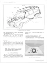
Figure 5 illustrates air distributor duct installation.
DEFROSTER DUCT
The defroster hose and outlet assemblies are illus
trated in Figure 6.
DEFROSTER
CABLE
£
AIR
CABLE
DEFROST-
AIR
TEMP
FAN SWITCH
CONTROL ASSEMBLY
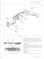
Removal (Fig. 7)
1. Remove the control assembly retaining screws at the
lower edge of the dash.
2. Lower the unit and remove the blower switch.
3. Remove the cables from the control unit one by one
and mount them in their respective positions on the
replacement unit. Check cable adjustment.
Installation
1. Attach the blower switch and wiring to the control
unit.
2. Place the unit in position in the dash and replace
mounting screws.
CONTROL CABLES
Remove the control assembly as outlined under CON
TROL ASSEMBLY and replace the affected cable or
cables. Check cable adjustment before installing control.
BLOWER SWITCH
Replacement (Fig. 7)
1. Disconnect the battery ground cable.
2. Disconnect the blower s w i t c h wiring harness
connector.
3. Remove the blower switch attaching screws and re
move the switch.
4. To install, reverse steps 1-3 above.
NOTE:
Be sure the switch arm plastic bushing
is in place and that the arm is installed in the
slot provided in the air-fan lever.
RESISTOR UNIT
Removal (Fig. 8)
1. Remove glove box assembly.
2. Unplug harness connector from resistor unit. Re
move the unit attaching screws and remove unit.
Installation
1. Place resistor unit in distributor duct and drive in
attaching screws. Connect harness connector to unit.
2. Install glove box assembly.
Fig. 7 — Heater Control
10-30 CHEVROLET TRUCK SERVICE MANUAL
Содержание 10 1971 Series
Страница 1: ......
Страница 96: ......
Страница 100: ...10 30 CHEVROLET TRUCK SERVICE MANUAL Fig 4 10 30 Series Truck Frame FRAME 2 4 ...
Страница 120: ......
Страница 203: ...ENGINE 6 25 Fig 22L Engine Mounts 10 30 CHEVROLET TRUCK SERVICE MANUAL ...
Страница 215: ...ENGINE 6 37 REAR M O U NT Fig 21V Engine Mounts 10 30 CHEVROLET TRUCK SERVICE MANUAL ...
Страница 218: ......
Страница 249: ......
Страница 250: ...EMISSION CONTROL SYSTEMS 6T 4 Fig 3 Combination Emission Control System Routing V8 10 30 CHEVROLET TRUCK SERVICE MANUAL ...
Страница 324: ......
Страница 339: ...FUEL TANK AND EXHAUST SYSTEMS 8 15 SPECIAL TOOLS Fig 22 Special Tools 1 J 23346 Fuel Tank Gauge Remover and Installer ...
Страница 340: ......
Страница 365: ...10 30 CHEVROLET TRUCK SERVICE MANUAL Fig 43 Power Steering Pump M ounting STEERING 9 25 ...
Страница 368: ......
Страница 386: ......
Страница 390: ...ELECTRICAL BODY AND CHASSIS 12 4 10 30 CHEVROLET TRUCK SERVICE MANUAL ...
Страница 391: ......
Страница 392: ...ELECTRICAL BODY AND CHASSIS 12 6 Fig 5 Rear Lighting Composite 10 30 CHEVROLET TRUCK SERVICE MANUAL ...
Страница 409: ...ELECTRICAL BODY AND CHASSIS 12 23 Fig 27 Engine Compartment CA30 02 10 30 CHEVROLET TRUCK SERVICE MANUAL ...
Страница 410: ...ELECTRICAL BODY AND CHASSIS 12 24 18DK GRN 19 Fig 28 Instrument Panel CA30 02 10 30 CHEVROLET TRUCK SERVICE MANUAL ...
Страница 411: ...ELECTRICAL BODY AND CHASSIS 12 25 Fig 29 Instrument Panel CA30 02 10 30 CHEVROLET TRUCK SERVICE MANUAL ...
Страница 412: ...ELECTRICAL BODY AND CHASSIS 12 26 fh Ar r kk 4 Fig 30 Engine Compartment C A K A 10 20 CA30 03 z _ ...
Страница 416: ...ELECTRICAL BODY AND CHASSIS 12 30 Fig 34 Engine Compartment CA KA10 20 CA30 04 10 30 CHEVROLET TRUCK SERVICE MANUAL ...
Страница 420: ...ELECTRICAL BODY AND CHASSIS 12 34 Fig 38 Engine Compartment C A K A 1 0 20 06 16 10 30 CHEVROLET TRUCK SERVICE MANUAL ...
Страница 422: ...ELECTRICAL BODY AND CHASSIS 12 36 Fig 40 Instrument Panel C A K A 10 20 06 16 10 30 CHEVROLET TRUCK SERVICE MANUAL ...
Страница 423: ...ELECTRICAL BODY AND CHASSIS 12 37 Fig 41 R ear Lamps C A K A 1 0 20 06 16 10 30 CHEVROLET TRUCK SERVICE MANUAL ...
Страница 424: ...ELECTRICAL BODY AND CHASSIS 12 38 Fig 42 Engine Compartment CA KA10 20 CAl30 14 34 10 30 CHEVROLET TRUCK SERVICE MANUAL ...
Страница 426: ...ELECTRICAL BODY AND CHASSIS 12 40 Fig 44 Instrument Panel CA KA10 20 CA30 14 34 10 30 CHEVROLET TRUCK SERVICE MANUAL ...
Страница 428: ......
Страница 432: ......
Страница 449: ...SPECIFICATIONS 9 10 30 CHEVROLET TRUCK SERVICE MANUAL ...
Страница 463: ......
Страница 464: ......
Страница 465: ......
Страница 466: ......


