


REAR SUSPENSION AND DRIVE LINE 4-11
CO MPONENT PARTS REPLACEMENT
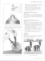
SERIES 10 3300, 3500 LB. CAPACITY AXLES
A N D SERIES 20 5500 LB. CAPACITY AXLES
AXLE ASSEMBLY (EXCEPT 5500 LB. D A N A AXLE)
Construction of the axle assembly is such that service
operations may be performed with the housing installed in
the vehicle or with the housing installed in a holding fix
ture. The following removal and installation procedure
is necessary only when the housing requires replacement.
NOTE:
All Axle attachments are important at
taching parts in that they could affect the perfor
mance of vital components and systems, and/or
could result in major repair expense. They must
be replaced with parts of the same part numbers
or with equivalent parts if replacement becomes
necessary. Do not use replacement parts of
lessor quality or substitute design. Torque
values must be used as specified during re
assembly to assure proper retention of these
parts.
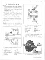
Removal
1. Raise vehicle on hoist.
2. Support rear axle assembly with suitable lifting
device, so that tension is relieved in springs, tie
rod, and shock absorbers.
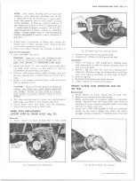
3. On vehicles so equipped, disconnect tie rod at axle
housing bracket or at differential carrier.
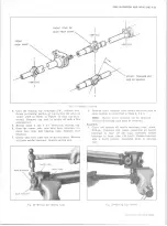
4. Remove trunnion bearing
“ XJ”
bolts from the axle
companion flange, separate trunnion from flange,
position propeller shaft to one side and tie it to
frame side rail.
NOTE:
Secure trunnion bearings caps to trun
nion, using masking tape or a large rubber band,
to prevent loss of bearings.
5. Disconnect shock absorbers at lower attachment
points and position out of the way.
6. Disconnect axle vent hose from vent connector and
position vent hose to one side.
7. Disconnect hydraulic brake hose at connector on axle
housing. Remove brake drum, disconnect parking
brake cable at actuating levers and at flange plate.
Refer to Section 5 for cable removal and brake
details.
8. On vehicles so equipped, check coil springs to make
sure that they are compressed; then on all vehicles,
remove axle
bolt nuts, “ U” bolts, spacers and
clamp plates.
9. Lower axle assembly and remove from vehicle.
Installation
1. Position axle assembly under vehicle and align with
springs or control arms as applicable.
2. Install spacer, clamp plate and
bolts to axle as
sembly, loosely install retaining nuts to
bolts.
3. Position shock absorbers in lower attachment brack
ets and loosely install nut to retain shock.
4. Connect axle vent hose to vent connector at carrier.
5. Connect hydraulic brake hose to connector on axle
housing, connect parking brake cable to actuating
levers. Install brake drum and wheel and tire as
sembly--bleed brakes and adjust parking brake as
outlined in applicable portion of Section 5.
6. Reassemble the propeller shaft to companion flange,
making sure that bearing caps are indexed in flange
seat. Install the torque bearing cap retaining nuts to
specifications.
7. Position vehicle so that weight is placed on suspen
sion c o m p o n e n t s and torque affected parts to
specifications.
8. Lower vehicle and remove from hoist.
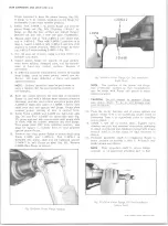
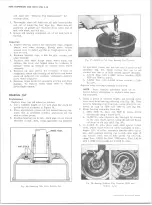
AXLE VENT
Replacement
The axle vent system consists of the vent connector,
vent hose and associated attaching parts. When replacing
vent hose make sure that it is routed along original path
in such a manner that the hose is free from kinks or
binds that would restrict air flow. In replacing the vent
connector; pry old connector from carrier, being sure
that entire connector is removed. Tap new connector into
carrier with a soft-faced hammer, prick punch around
edge of hole to insure fit of new connector (fig. 30).
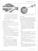
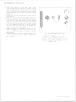
AXLE SHAFT (EXCEPT 5500 LB. D A N A AXLE)
Removal
1. Raise vehicle on hoist. Remove wheel and tire as
sembly and brake drum.
2. Clean all dirt and foreign material from area of
carrier cover.
3. Loosen carrier cover-to-carrier bolts slightly to al
low lubricant to drain from carrier. Remove carrier
cover and gasket.
4. Remove the differential pinion shaft lockscrew and
the differential pinion shaft (fig. 18).
5. Push flanged end of axle shaft toward center of
vehicle and remove “ C” lock from button end of
shaft.
6. Remove axle shaft from housing, being careful not to
damage oil seal at end of housing.
Fig. 18— Differential Pinion Shaft Removal
CHEVROLET TRUCK SERVICE MANUAL
Содержание 10 1971 Series
Страница 1: ......
Страница 96: ......
Страница 100: ...10 30 CHEVROLET TRUCK SERVICE MANUAL Fig 4 10 30 Series Truck Frame FRAME 2 4 ...
Страница 120: ......
Страница 203: ...ENGINE 6 25 Fig 22L Engine Mounts 10 30 CHEVROLET TRUCK SERVICE MANUAL ...
Страница 215: ...ENGINE 6 37 REAR M O U NT Fig 21V Engine Mounts 10 30 CHEVROLET TRUCK SERVICE MANUAL ...
Страница 218: ......
Страница 249: ......
Страница 250: ...EMISSION CONTROL SYSTEMS 6T 4 Fig 3 Combination Emission Control System Routing V8 10 30 CHEVROLET TRUCK SERVICE MANUAL ...
Страница 324: ......
Страница 339: ...FUEL TANK AND EXHAUST SYSTEMS 8 15 SPECIAL TOOLS Fig 22 Special Tools 1 J 23346 Fuel Tank Gauge Remover and Installer ...
Страница 340: ......
Страница 365: ...10 30 CHEVROLET TRUCK SERVICE MANUAL Fig 43 Power Steering Pump M ounting STEERING 9 25 ...
Страница 368: ......
Страница 386: ......
Страница 390: ...ELECTRICAL BODY AND CHASSIS 12 4 10 30 CHEVROLET TRUCK SERVICE MANUAL ...
Страница 391: ......
Страница 392: ...ELECTRICAL BODY AND CHASSIS 12 6 Fig 5 Rear Lighting Composite 10 30 CHEVROLET TRUCK SERVICE MANUAL ...
Страница 409: ...ELECTRICAL BODY AND CHASSIS 12 23 Fig 27 Engine Compartment CA30 02 10 30 CHEVROLET TRUCK SERVICE MANUAL ...
Страница 410: ...ELECTRICAL BODY AND CHASSIS 12 24 18DK GRN 19 Fig 28 Instrument Panel CA30 02 10 30 CHEVROLET TRUCK SERVICE MANUAL ...
Страница 411: ...ELECTRICAL BODY AND CHASSIS 12 25 Fig 29 Instrument Panel CA30 02 10 30 CHEVROLET TRUCK SERVICE MANUAL ...
Страница 412: ...ELECTRICAL BODY AND CHASSIS 12 26 fh Ar r kk 4 Fig 30 Engine Compartment C A K A 10 20 CA30 03 z _ ...
Страница 416: ...ELECTRICAL BODY AND CHASSIS 12 30 Fig 34 Engine Compartment CA KA10 20 CA30 04 10 30 CHEVROLET TRUCK SERVICE MANUAL ...
Страница 420: ...ELECTRICAL BODY AND CHASSIS 12 34 Fig 38 Engine Compartment C A K A 1 0 20 06 16 10 30 CHEVROLET TRUCK SERVICE MANUAL ...
Страница 422: ...ELECTRICAL BODY AND CHASSIS 12 36 Fig 40 Instrument Panel C A K A 10 20 06 16 10 30 CHEVROLET TRUCK SERVICE MANUAL ...
Страница 423: ...ELECTRICAL BODY AND CHASSIS 12 37 Fig 41 R ear Lamps C A K A 1 0 20 06 16 10 30 CHEVROLET TRUCK SERVICE MANUAL ...
Страница 424: ...ELECTRICAL BODY AND CHASSIS 12 38 Fig 42 Engine Compartment CA KA10 20 CAl30 14 34 10 30 CHEVROLET TRUCK SERVICE MANUAL ...
Страница 426: ...ELECTRICAL BODY AND CHASSIS 12 40 Fig 44 Instrument Panel CA KA10 20 CA30 14 34 10 30 CHEVROLET TRUCK SERVICE MANUAL ...
Страница 428: ......
Страница 432: ......
Страница 449: ...SPECIFICATIONS 9 10 30 CHEVROLET TRUCK SERVICE MANUAL ...
Страница 463: ......
Страница 464: ......
Страница 465: ......
Страница 466: ......


