


FRONT SUSPENSION 3-3
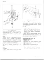
Fig. 2— Front- End Alignment
6. The frame corrected angle, Step 3, should correspond
to the recommended angle on the chart within ±1
Make changes as necessary to bring caster angle
within limits.
Camber
1. Determine v e h i c l e camber angle on alignment
machine.
2. Measure dimension
“A” .
3. Using dimension
“ A”
and the cdster-camber chart
for the appropriate vehicle, find the recommended
camber angle.
4. If the angle in Step 1 does not correspond to the rec
ommended angle on the chart within ±1°, make neces
sary changes.
Shims may be changed at either front or reai: to vary
caster, or at both points equally to vary camber (fig. 5).
Toe-In
Toe-in is the amount in fractions of an inch that Wheels
are closer together in front than at rear. Check steering
gear high point adjustment and place wheels in straight
ahead position before checking toe-in. Adjustments are
made by loosening clamp bolts at each end of tie rod,
then turning tie rod tube until wheels have proper toe-in.
Tighten clamp bolts to specifications (See Section 9) after
proper adjustment is made.
Steering Axis Inclination
Steering axis inclination is the tilt of the steering
knuckle. If the inclination is not within the specified
limits, the steering knuckle is bent and must be replaced.
CO M PO NENT PARTS REPLACEMENT
NOTE:
All front suspension attachments are im
portant attaching parts in that they could affect
the performance of vital components and sys
tems, and/or could result in major repair ex
pense. They must be replaced with parts of the
same part numbers or with equivalent parts if
replacement becomes necessary. Do not use
replacement parts of lesser quality or substitute
design. Torque values must be used as specified
during reassembly to assure proper retention of
these parts.
WHEEL HUBS, BEARINGS
Removal (Fig. 6)
1. Raise vehicle on hoist and remove wheel and tire
assembly. Remove dust cap from end of hub and
withdraw cotter pin.
2. Remove the brake caliper.
3. Remove hub and disc assembly.
4. Remove outer bearing from hub. The inner bearing
will remain in the hub and may be removed by prying
out the inner grease seal.
5. Wash all parts in cleaning solvent.
Inspection
1. Check all bearings for cracked bearing cages, worn
or pitted rollers.
2. Check bearing races for cracks or scoring, check
brake drums for out-of-round or scored condition
and check bearing outer races for looseness in hubs.
Repairs
Replacem ent of Bearing Cups
If necessary to replace an outer race, drive out old
race from the hub with a brass drift inserted behind race
in notches in hub. Install new race by driving it into hub
with the proper race installer. Remove the inner race
in the same manner.
NOTE:
Use care when installing new race to
start it squarely into hub, to avoid distortion and
possible cracking.
Thoroughly lubricate bearing assemblies with new high
melting point wheel-bearing lubricant. Remove any ex
cess lubricant.
NOTE:
Be sure bearing parts have been thor
oughly cleaned and air-dried.
W heel Stud Replacement (Fig. 7)
NOTE:
Use a piece of water pipe or other
similar tool to support the hub while pressing a
wheel stud either in or out.
Installation
1. Pack inner and outer wheel bearings with recom
mended grease (see Seciton 0).
2. Place inner bearing in hub and install new seal
assembly (or assemblies), tapping into place with
soft hammer.
3. Position hub on spindle and install outer bearing,
pressing it firmly into position in hub.
10-30 CHEVROLET TRUCK SERVICE MANUAL
Содержание 10 1971 Series
Страница 1: ......
Страница 96: ......
Страница 100: ...10 30 CHEVROLET TRUCK SERVICE MANUAL Fig 4 10 30 Series Truck Frame FRAME 2 4 ...
Страница 120: ......
Страница 203: ...ENGINE 6 25 Fig 22L Engine Mounts 10 30 CHEVROLET TRUCK SERVICE MANUAL ...
Страница 215: ...ENGINE 6 37 REAR M O U NT Fig 21V Engine Mounts 10 30 CHEVROLET TRUCK SERVICE MANUAL ...
Страница 218: ......
Страница 249: ......
Страница 250: ...EMISSION CONTROL SYSTEMS 6T 4 Fig 3 Combination Emission Control System Routing V8 10 30 CHEVROLET TRUCK SERVICE MANUAL ...
Страница 324: ......
Страница 339: ...FUEL TANK AND EXHAUST SYSTEMS 8 15 SPECIAL TOOLS Fig 22 Special Tools 1 J 23346 Fuel Tank Gauge Remover and Installer ...
Страница 340: ......
Страница 365: ...10 30 CHEVROLET TRUCK SERVICE MANUAL Fig 43 Power Steering Pump M ounting STEERING 9 25 ...
Страница 368: ......
Страница 386: ......
Страница 390: ...ELECTRICAL BODY AND CHASSIS 12 4 10 30 CHEVROLET TRUCK SERVICE MANUAL ...
Страница 391: ......
Страница 392: ...ELECTRICAL BODY AND CHASSIS 12 6 Fig 5 Rear Lighting Composite 10 30 CHEVROLET TRUCK SERVICE MANUAL ...
Страница 409: ...ELECTRICAL BODY AND CHASSIS 12 23 Fig 27 Engine Compartment CA30 02 10 30 CHEVROLET TRUCK SERVICE MANUAL ...
Страница 410: ...ELECTRICAL BODY AND CHASSIS 12 24 18DK GRN 19 Fig 28 Instrument Panel CA30 02 10 30 CHEVROLET TRUCK SERVICE MANUAL ...
Страница 411: ...ELECTRICAL BODY AND CHASSIS 12 25 Fig 29 Instrument Panel CA30 02 10 30 CHEVROLET TRUCK SERVICE MANUAL ...
Страница 412: ...ELECTRICAL BODY AND CHASSIS 12 26 fh Ar r kk 4 Fig 30 Engine Compartment C A K A 10 20 CA30 03 z _ ...
Страница 416: ...ELECTRICAL BODY AND CHASSIS 12 30 Fig 34 Engine Compartment CA KA10 20 CA30 04 10 30 CHEVROLET TRUCK SERVICE MANUAL ...
Страница 420: ...ELECTRICAL BODY AND CHASSIS 12 34 Fig 38 Engine Compartment C A K A 1 0 20 06 16 10 30 CHEVROLET TRUCK SERVICE MANUAL ...
Страница 422: ...ELECTRICAL BODY AND CHASSIS 12 36 Fig 40 Instrument Panel C A K A 10 20 06 16 10 30 CHEVROLET TRUCK SERVICE MANUAL ...
Страница 423: ...ELECTRICAL BODY AND CHASSIS 12 37 Fig 41 R ear Lamps C A K A 1 0 20 06 16 10 30 CHEVROLET TRUCK SERVICE MANUAL ...
Страница 424: ...ELECTRICAL BODY AND CHASSIS 12 38 Fig 42 Engine Compartment CA KA10 20 CAl30 14 34 10 30 CHEVROLET TRUCK SERVICE MANUAL ...
Страница 426: ...ELECTRICAL BODY AND CHASSIS 12 40 Fig 44 Instrument Panel CA KA10 20 CA30 14 34 10 30 CHEVROLET TRUCK SERVICE MANUAL ...
Страница 428: ......
Страница 432: ......
Страница 449: ...SPECIFICATIONS 9 10 30 CHEVROLET TRUCK SERVICE MANUAL ...
Страница 463: ......
Страница 464: ......
Страница 465: ......
Страница 466: ......


