background image

RM245 Series


System Components Removal and Installation


19 


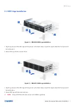
2-2 HDD Cage Installation


Figure 14


  RM24508 HDD cage installation


1. Align the guide pins of the HDD cage with the grooves on the chassis base, and push this cage backward the front panel until 

    locked into place.   

2. Secure this cage with two screws as shown. 


Figure 15 


RM24512 HDD cage installation


1. Align the guide pins of the HDD cage with the grooves on the chassis base, and push this cage backward the front panel until 

    locked into place.   

2. Secure HDD cage with two screws as shown. 


NOTE: 


All cage SKUs follow the same removal and installation guidelines.


Содержание RM245 Series

Страница 1: ...RM245 Series Rackmount Chassis User Manual April 2020 Version 1 2 A document provides an overview of product features functions architecture and support specifications...

Страница 2: ...performance course of dealing or usage in trade This document contains information on products services and or processes in development All information provided here is subject to change without noti...

Страница 3: ...8 2 2 HDD Cage Installation 19 2 3 Hot swap HDD Assembly Maintenance 20 2 4 Internal 2 5 HDD Installation Removal 26 2 5 Slim ODD Installation Removal 27 2 6 System Maintenance 28 2 7 Fan Assembly Ins...

Страница 4: ...re 19 3 5 HDD removal tool less type 21 Figure 20 3 5 HDD installation screw type 22 Figure 21 3 5 HDD removal screw type 22 Figure 22 2 5 HDD installation in 3 5 tray screw type 23 Figure 23 2 5 HDD...

Страница 5: ...SU cage installation 37 Figure 49 CRPS module installation 38 Figure 50 CRPS module removal 38 Figure 51 Slide rail Installation 1 384 23803 3300A0 39 Figure 52 Slide rail Installation 2 384 23803 330...

Страница 6: ...le 8 Backplane specifications 43 Table 9 Connector and pin header function description 44 Table 10 Dip switch setting 45 Table 11 Fan setting for RM24512 45 Table 12 Backplane specifications 46 Table...

Страница 7: ...x 438 0 x 87 00 mm 21 95 x 17 24 x 3 43 Drive Bay RM24508 8 x 3 5 Hot swap 2 x 2 5 Internal 1 x Slim ODD RM24512 12 x 3 5 Hot swap 2 x 2 5 Hot swap Option for CRPS Only Storage Backplane RM24508 3 5...

Страница 8: ...RM245 Series Product Overview 8 1 1 System Outlook Overview Figure 1 RM24508 overview Figure 2 RM24512 overview...

Страница 9: ...M24508 major components overview Figure 4 RM24512 major components overview A Front Top Cover B Back Top Cover C Label Embossing D Fan Assembly E Server Board F Power Supply Unit G Slim ODD Bay H Inte...

Страница 10: ...RM245 Series Product Overview 10 1 2 Front Panel Figure 5 RM24508 front panel Figure 6 RM24512 front panel A Front Control Panel B Storage Drive Bay C Info Tag D Rack Handles E Slim ODD Bay...

Страница 11: ...ew 11 1 3 Back Panel Figure 7 Back panel with single PSU Figure 8 Back panel with redundant PSU A 2U Single Power Supply B CRPS C I O Gasket D Low Profile Expansion Slots E Full Height Expansion Slots...

Страница 12: ...l Panel Figure 9 Front control panel Table 2 Front control panel Label ICON Indicator button or connector A PowerButton B UIDButton C ResetButton D USB3 0 E HDDActivityLED F SystemAlarmLED G LAN1 LAN2...

Страница 13: ...RM245 Series Product Overview 13 1 5 Chassis Dimensions Figure 10 Chassis dimensions Figure 11 Label embossing dimensions...

Страница 14: ...of the server in the rack may result in failure of the rack rails causing damage to the system or personal injury Two people to operate or the use of a mechanical assist tool to install and align the...

Страница 15: ...ting HDD class Class 1 Highest performance reliability and data integrity Class 2 A second tier of performance reliability and data integrity HDD I O throughput degradation SPEC Pass Fail Criteria No...

Страница 16: ...ment Table 5 System packaging information Part Number Single Bulk Form Factor mm Support level 387 24512 3300A0 Single 730 x 590 x 190 L5 NOTE The design of the inner packaging components does not pre...

Страница 17: ...x 3 5 hot swap SAS SATA HDD or 2 5 SAS SATA HDD or SSD RM24508 Up to 12 x 3 5 hot swap SAS SATA HDD or 2 5 SAS SATA HDD or SSD RM24512 2 x 2 5 hot swap SATA HDD SSD 7 mm or 9 5 mm thickness or NVMe 7...

Страница 18: ...r with the grooves on the chassis base and slide it toward the front panel until locked into place 2 Secure this cover with two screws as shown Figure 13 Rear top cover installation 1 Align the guide...

Страница 19: ...push this cage backward the front panel until locked into place 2 Secure this cage with two screws as shown Figure 15 RM24512 HDD cage installation 1 Align the guide pins of the HDD cage with the groo...

Страница 20: ...swap HDD assembly installation 1 With the lever open insert the HDD assembly into the drive bay until the end of the HDD cage 2 Push down the lever to lock it into place Figure 17 3 5 Hot swap HDD as...

Страница 21: ...t of the HDD tray 2 Push down the HDD when it is locked into place Figure 19 3 5 HDD removal tool less type 1 Bottom up the HDD assembly and loosen the screw as shown 2 Press out the HDD by your two t...

Страница 22: ...tallation 22 Figure 20 3 5 HDD installation screw type 1 Align the HDD with the anchor point on the tray 2 Secure the tray by four screws as shown Figure 21 3 5 HDD removal screw type 1 Loosen four sc...

Страница 23: ...ive bays are suggested to populate with a 3 5 drive tray where it is supposed to be installed with a 3 5 drive a 2 5 drive with plastic dummy filler or only dummy fillers In addition in order to suppo...

Страница 24: ...allation 1 With the lever open insert the HDD assembly into the drive bay until the end of the HDD cage 2 Push down the lever when it is secured into place Figure 25 2 5 hot swap HDD assembly removal...

Страница 25: ...r flow requirements all front drive bays must be populated with a drive carrier Drive carriers must be installed with either a drive or supplied drive blank NOTE There are drive carriers to support 2...

Страница 26: ...g four pins with the dimples on one side of the HDD 2 Align the two dimples of the other side of the HDD assembly with the two hooks on the HDD cage as shown 3 Push down the HDD assembly until it is s...

Страница 27: ...stallation 1 Secure the plastic bracket onto the slim ODD with two screws 2 Insert the slim ODD assembly into the drive bay and push it until secured into place Figure 30 RM24508 internal slim ODD rem...

Страница 28: ...des and push the system all the way into the cabinet 2 Open and hold the latches on both sides as shown 3 Secure the screws in the latches on both sides Figure 32 Removal of whole system from the rack...

Страница 29: ...base matched on both sides 2 Secure the fan assembly with thumb screws on both sides as shown Figure 34 RM24508 fan holder installation 1 Ensure the air flow direction pointers on the fan and the fan...

Страница 30: ...35 RM24508 fan module installation 1 Insert the fan module into the fan cage until the tabs locked into place 2 Secure the fan module with one screw as shown Figure 36 RM24508 air baffle installation...

Страница 31: ...ace 3 Connect the related fan connectors Figure 38 RM24512 fan holder installation 1 Ensure the air flow direction pointers on the fan and the fan holder are in the same direction as shown 2 Firmly co...

Страница 32: ...2 fan module installation 1 Insert the fan module into the fan cage until secured into place NOTE All the fan modules are inserted as the direction pointers indicate Figure 40 RM24512 air baffle insta...

Страница 33: ...e bottom of the chassis and ensure the alignment of screw holes matched 2 Secure the bracket with two screws from the outside of the chassis Figure 42 Drive cage installation back panel 1 Insert the c...

Страница 34: ...Removal and Installation 34 Figure 43 Drive backplane installation back panel 1 Attach the backplane to the rear of the drive cage as shown 2 Ensure the backplane firmly engaged with the cage 3 Secur...

Страница 35: ...shown Figure 45 Cards and brackets installation 3 Align the three screw holes of the riser card with T nails on the bracket and slide the riser card into place as shown 4 Secure the riser card with o...

Страница 36: ...and Removal Figure 46 Single 2U PSU installation 1 Install the PSU into the chassis and ensure alignment of screw holes on the PSU the chassis base and the back panel matched 2 Secure the PSU with the...

Страница 37: ...of the cage as shown 2 Attach the PSU bracket to PSU cage and secure it by two screws 3 Install the PSU Cage into the chassis and ensure the alignment of screw holes and brackets matched Figure 48 Re...

Страница 38: ...on 38 Figure 49 CRPS module installation 1 Insert the CRPS module into the PSU cage and push until it is secured into place Figure 50 CRPS module removal 1 Press the latch without release as shown 2 P...

Страница 39: ...gure 51 Slide rail Installation 1 384 23803 3300A0 1 Attach the inner rail to the chassis base while aligning the T pins on the side of the system with the slots on the inner rail Figure 52 Slide rail...

Страница 40: ...emoval and Installation 40 Figure 53 Slide rail Installation 3 384 23803 3300A0 3 Lift the latch as shown 4 Secure the inner rail with one screw Figure 54 Slide rail Installation 4 384 23803 3300A0 5...

Страница 41: ...N LED Color Behavior Condition A C Power LED Blue Stay off Fault Solid on Present B D Activity LED Green Blink Access Status LED Red Solid on Failure 1Hz blink Rebuild 4Hz blink Locate NOTE The drive...

Страница 42: ...TA backplane All available SAS SATA backplanes include the following common features 12Gbps SAS and 6Gbps SAS SATA 29 pin SFF 8680 12Gbps rated drive interface connectors providing both power and I O...

Страница 43: ...nt Activity LED Green on Access Red on Failure Red 1Hz blink Rebuild Red 4Hz blink Locate Environment Monitor Temperature senor TMP75 detection Connector 1 12 x SFF 8680 2 2 x Mini SAS HD 3 2 x 8 pin...

Страница 44: ...B Mini SAS HD The backplane includes two multi port Mini SAS cable connectors providing data signals for twelve SAS SATA drives on the backplane A cable can be routed from matching connectors on the s...

Страница 45: ...ch setting PIN Number PIN Definition ON OFF 1 SYS FAN 2 4 2 PWM EN DISABLE 3 TEMP ALRAM 55 65 4 SYS FAN EN DISABLE 5 BUZZER EN DISABLE 6 SES MON EN DISABLE 7 8 I2C ADDR SET SET Table 11 Fan setting fo...

Страница 46: ...ED Green on Access Red on Failure Red 1Hz blink Rebuild Red 4Hz blink Locate Environment Monitor Temperature senor TMP75 detection Connector 1 12 x SFF 8680 2 3 x Mini SAS HD 3 2 x 8 pin ATX Mini Fit...

Страница 47: ...ower supply B Mini SAS HD The backplane includes three multi port Mini SAS cable connectors providing data signals for twelve SAS SATA drives on the backplane A cable can be routed from matching conne...

Страница 48: ...tion Drawing MBPWMConnector 1 MBTACH Output FANClockOutputtoMB 2 MBPWM Input FANPWMInputfromMB Table 15 Dip switch setting PIN Number PIN Definition ON OFF 1 FAN1 EN DISABLE 2 FAN2 EN DISABLE 3 FAN3 E...

Страница 49: ...Connector 1 8xSFF 8680 2 2xMini SASHD 3 1x8 pin ATX Mini Fit power connectors for 12V only 4 4x4 pinfan 5 1x4 pinI2C 6 1x1 pinSMDswitch 7 4x4 pin2 54mmWafer 8 1x4 pin2 5mmWafer Dimension LxWxH 432 0x5...

Страница 50: ...lane includes two multi port mini SAS cable connectors providing data signals for eight SAS SATA drives on the backplane A cable can be routed from matching connectors on the server board or add in SA...

Страница 51: ...RM245 Series Backplane 51 Table 18 Fan setting for RM24508 DIP NC3 Mute pin JA1 JCK pin Fan ON PIN 5 6 OPEN PIN 4 6 SHORT 4 ON PIN 5 6 OPEN PIN 2 4 SHORT 2 ON PIN 5 6 SHORT N A No matter what status 3...

Страница 52: ...ase temperature rating of 70 C 1 or 2 SATA SSDs supporting up to 1 5 W per device with a case temperature rating of 60 C 2 The maximum supported SSD power and thermal limits documented above were base...

Страница 53: ...torage devices online Display LED indicates storage device status Power LED Off Fault Blue on Present Activity LED Green on Access Red on Failure Red 1Hz blink Rebuild Red 4Hz blink Locate Environment...

Страница 54: ...used as a management interface to the server board B SATA 7 pin The backplane includes two SATA 7 pin connectors providing data signals for two SAS SATA drives on the backplane A cable can be routed f...

Страница 55: ...ht to examine the DOA products If the damage of DOA products is caused by improper action as described above the customer will be liable for paying the related charge having occurred or paying the fee...

Отзывы: