RM238 Series
Backplane
│
62
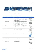
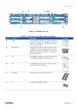
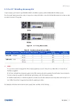
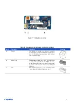
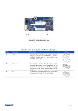
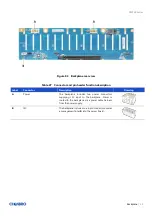
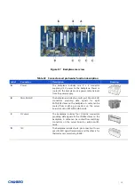
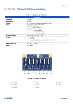
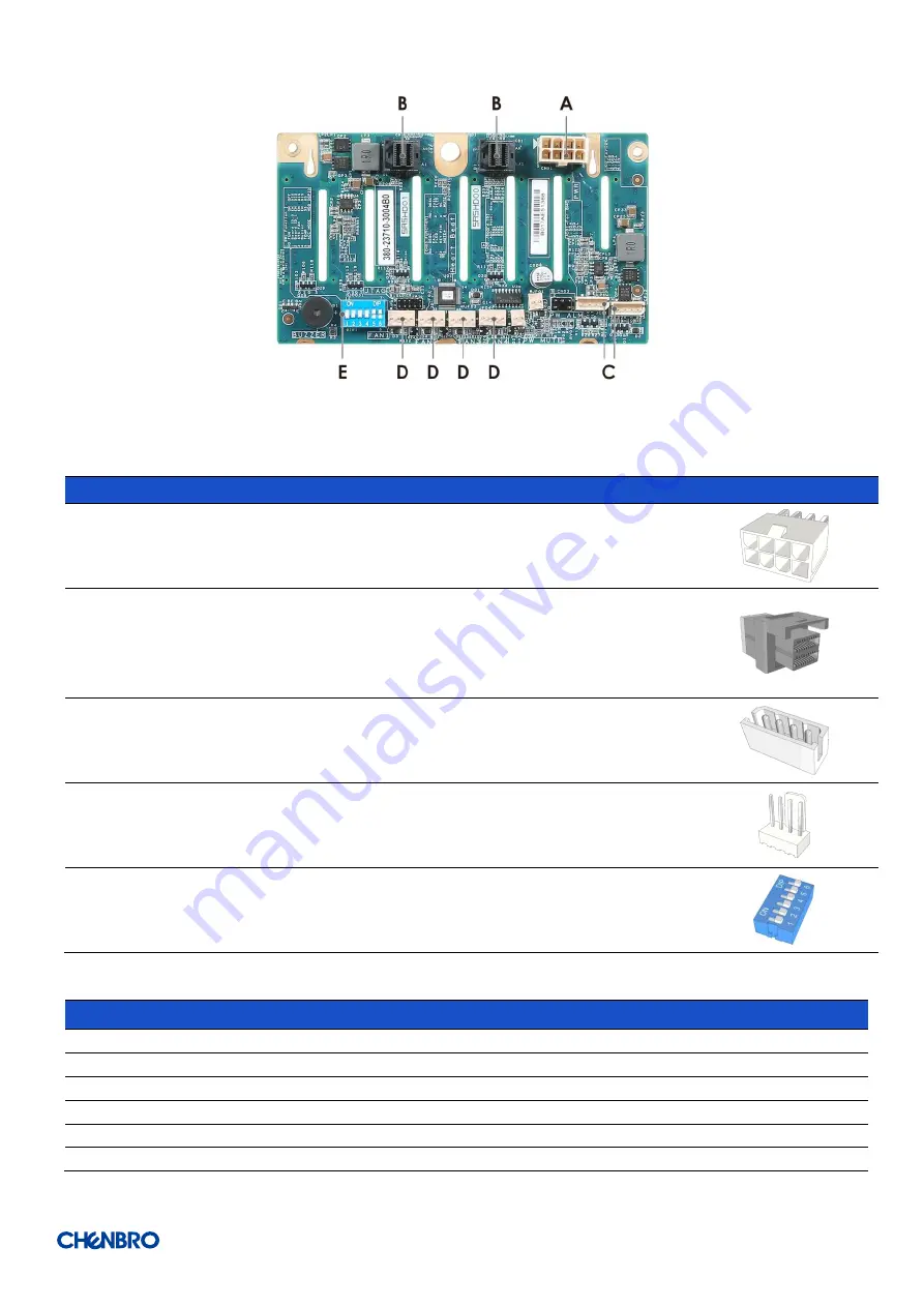
Figure 81 Backplane rear view
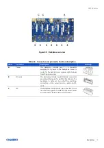
Table 24 Connector and pin header function description
Label
Connector
Description
Drawing
A
Power
The backplane includes one power connector
supplying 12V input to the backplane. Power is
routed to the backplane via a power cable harness
from the power supply.
B
Mini-SAS HD
The backplane includes two multi-port Mini-SAS HD
connectors providing data signals for eight
SATA/SAS drives on the backplane. A cable can be
routed from matching connectors on the server
board or add-in SATA/SAS HBA cards.
C
I2C
The backplane includes two 4-pin connectors. One is
used as a management interface to the server board
and the other is for BP to BP communication.
D
Fan
The backplane includes four fan connectors used to
control and monitor fan speed.
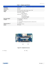
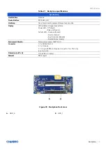
E
DIP Switch
Follow below the DIP switch setting table.
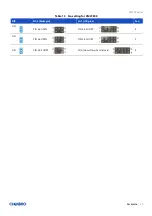
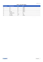
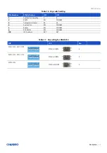
Table 25
Dip switch setting
PIN-Number
PIN-Definition
ON
OFF
1
Board ID 0
EN
DISABLE
2
Board ID 1
EN
DISABLE
3
System Fan
EN
DISABLE
4
Buzzer Alarm
EN
DISABLE
5
Temperature Alarm
55
65
6
ACC Mode
HDD
SGPIO