73
9. APPENDIX
9.1. MEASUREMENTS
9.1.1. DEFINITION
Calculations are done according to IEC 61557-12 and IEC 61000-4-30.
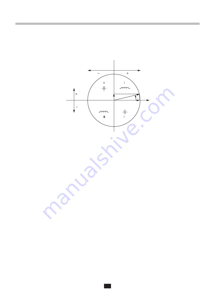
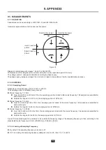
Geometric representation of active and reactive power:
Figure 39
Diagram in accordance with clauses 12 and 14 of IEC 60375.
The reference of this diagram is the current vector (fixed on the right-hand part of the axis).
The voltage vector V changes its direction according to phase angle
ϕ
.
The phase angle
ϕ
between voltage V and current I is taken to be positive in the the counterclockwise sense.
9.1.2. SAMPLING
9.1.2.1.
Sampling Period
Depends on mains frequency: 50 Hz, 60 Hz or 400 Hz.
The sampling period is calculated every second.
Mains frequency f = 50 Hz
From 42.5 to 57.5 Hz (50 Hz ±15%), the sampling period is locked to the mains frequency. 128 samples are available for
each mains cycle.
Outside the range 42.5 to 57.5 Hz, the sampling period is 128*50 Hz.
Mains frequency f = 60 Hz
From 51 to 69 Hz (60 Hz ±15%), the sampling period is locked to the mains frequency. 128 samples are available for
each mains cycle.
Outside the range 51 to 69 Hz, the sampling period is 128*60 Hz.
Mains frequency f = 400 Hz
From 340 to 460 Hz (400 Hz ±15%), the sampling period is locked to the mains frequency. 16 samples are available for
each mains cycle.
Outside the range 340 to 460 Hz, the sampling period is 16*400 Hz.
A pure DC measured signal is considered to be outside the frequency ranges. The sampling frequency is then, according to the
preselected mains frequency, 6.4 kHz (50/400 Hz) or 7.68 kHz (60 Hz).
9.1.2.2.
Locking of Sampling Frequency
By default, the sampling frequency is locked to V1
If V1 is missing, the sampling frequency attempts to lock to V2, then V3, I1, I2 and I3
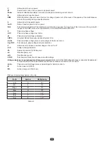
V
P
φ
S
Q
Export active power
Import active power
Import reactive
power
Export reactive
power
Содержание pel 102
Страница 1: ...Power energy logger EN User s manual PEL 102 PEL 103 PEL 104 ...
Страница 24: ...24 Aggregation period Date and time IP address scrolling Wi Fi address scrolling PEL104 ...
Страница 34: ...34 Two phase 3 wire 2P 3W V1 V2 U12 VN P Q S PF P Q S tan ϕ ϕ V2 V1 ϕ I1 V1 ϕ I2 V2 I1 I2 f ϕ I2 I1 ...
Страница 36: ...36 Three phase 3 wire balanced 3P 3W b U12 U23 U31 f P Q S PF P Q S tan ϕ I1 I2 I3 ϕ I1 U12 ...
Страница 38: ...38 Three phase 4 wire wye balanced 3P 4WYb I1 I2 I3 V1 V2 V3 VN U12 U23 U31 f P Q S tan ϕ ...
Страница 39: ...39 DC 2 wire dC 2W DC 3 wire dC 3W P Q S PF ϕ I1 V1 P Q S tan ϕ P I V VN I1 I2 IN ...
Страница 40: ...40 DC 4 wire dC 4W P I1 I2 I3 IN V1 V2 V3 VN V1 V2 VN ...
Страница 48: ...48 Two phase 3 wire 1P 3W I1 I2 V1 V2 U12 VN P Q S P Q S ...
Страница 49: ...49 Three phase 3 wire 3P 3W 2 3P 3W 3 3P 3WO2 3P 3WO3 3P 3WY2 3P 3WY3 3P 3W b I1 I2 I3 U12 U23 U31 P Q S P Q S ...
Страница 51: ...51 P Q S ...
Страница 85: ...85 ...






![Lambrecht power[cube] 30.95800.015000 Manual preview](http://thumbs.mh-extra.com/thumbs/lambrecht/power-cube-30-95800-015000/power-cube-30-95800-015000_manual_3388101-01.webp)


