

LT-WIC101010
3
rd
Printing
Page 7 of 16
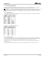
3.5.
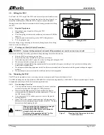
Lifting the WIC
See Table 1 for WIC weight. The WIC can be moved by either forklift or crane.
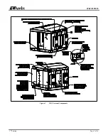
If using a forklift, remove the panel on the front, below the door (Figure 3) to
access the forklift pockets. When the WIC is in place, replace this panel.
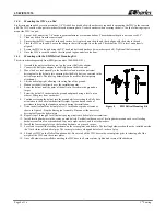
If using a crane, then Charles recommends the following procedure for lifting
the WIC.
3.5.1.
Required Equipment
One derrick (crane) capable of lifting the WIC
Spreader bars
Four lifting slings or chains with each having a minimum 10,000 lbs.
capacity
Connecting links to attach slings to the WIC’s lifting brackets
75-ft. long tagline rope
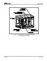
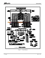
Insert the lifting sling connecting links securely through each of the lifting
brackets as shown in Figure 6.
3.5.2.
Warnings and Specific Safety Precautions
WARNING
Improper hoisting equipment and unsafe lifting procedures can result in serious injury or death
Observe the following local safety procedures when performing the tasks in this section.
Keep the WIC away from any power lines.
Keep bystanders away from the work operations at all times.
Only trained operators shall operate the crane for lifting and setting the WIC.
Do not suspend loads over people or equipment.
All persons working with hoisting equipment shall wear standard safety gear according to local practices including safety
helmets and steel-toed shoes.
Do not operate the hoisting equipment until all stabilizer are extended and in firm contact with the ground or adequate support
structure.
Do not attempt to retract or extend the stabilizers while a load is suspended.
3.6.
Mounting the WIC
The WIC can be mounted on a new or existing concrete or composite pad. Ensure that the unit is level.
Two EMI mounting kits are also available (1000-0000-0101 helical mounting assembly or 1000-0000-0162 gravity mounting kit). See the
documentation that ships with the kit for mounting instructions.
3.6.1.
Constructing a New Pad
Use only concrete for new pad construction. Do not use substitute
materials since they lack the rigidity for WIC placement.
Observe local building practices for pad construction. Charles
recommends that the pad should extend a minimum of 8” beyond
the WIC base on all sides.
Use a minimum of 6” of sand or gravel as a base for the pad for
leveling purposes.
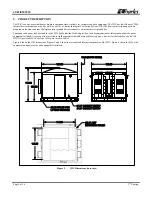
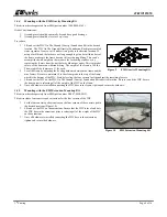
Figure 7 shows the required conduit openings and mounting hole
dimensions for entering/mounting the bottom of the WIC. Use these
dimensions when designing the pad.
WARNING
When pad mounting, the compression strength
of the pad must be at least 4000 psi as
determined by ASTM C39 test of compression
strength of concrete cylinders.
The slump of the concrete shall be 2” to 4” as
determined by ASTM C143 test method.
Figure 6
Lifting the WIC
Figure 7
Mounting Hole Dimensions (in inches)
Viewed from Above