background image

CHA F-LOOP 3.0 

Page 

9


u.


3/8” Antenna Mount

 - 

The 3/8” Antenna Mount is an unthreaded hole at the r

ear of the 

Aluminum Base Plate (n) that enables attachment of the CHA F-LOOP 3.0 to any 

3/8”

 antenna 

mount using a 3/8” x 24 

hex bolt. 


v.


Duffel Bag 

 The military-style Duffel Bag 

(not shown)

, is included with all models and is used to 

store the components of the CHA F-LOOP 3.0 when not deployed.  It is incredibly versatile and 
can also be used as a backpack. 


Standard Single Flexible Loop Assembly (CHA F-LOOP 3.0 BASIC) 

The Standard Single Flexible Loop configuration uses the standard Flexible Radiator Loop (b) and small 
Coupling Loop (c) included with the CHA F-LOOP 3.0 BASIC, CHA FLOOP 3.0 PLUS, and CHA F-FLOOP 3.0 
TOTAL antennas.   
The CHA F-LOOP 3.0 BASIC antenna should be installed near the radio set; either indoors or in a sheltered 
outside area, such as a balcony or porch. Because the magnetic component of an electromagnetic wave 
is maximum at the boundary between the ground and the space above, loop performance is usually best 
when the loop is located near the gr

ound at a distance outside of the loop’s close

-in induction field (just 

a loop diameter or two).  The CHA F-LOOP 3.0 BASIC is not waterproof and must be installed in an area 
protected from the weather.  Do not use an antenna tuner or coupler with this antenna, as it may cause 
you to mistune the antenna.  

Perform the following steps to assemble the Standard Single Flexible Loop configuration. 

1.


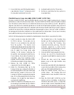
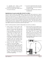
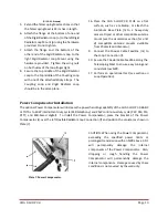
Select  a  location  to  setup  the  CHA  F-LOOP 
3.0  BASIC  antenna.    The  location  can  be 
indoors  or  in  an  outdoors  area  protected 
from  the  weather.    The  location  must 
facilitate accessibility by the operator to the 
Tuning  Knob  (h).  The  operator  needs  to  be 
able  to  adjust  the  Tuning  Knob  while 
listening  to  the  receiver,  activating  the 
transmitter,  and  observing  the  SWR  meter.  
If used indoors, the location should also be 
reasonably  away  from  switching  power 
supplies, Internet routers, and other sources 
of electrical and electronic interference. 

2.


Remove  the  CHA  F-LOOP  3.0  BASIC 
components from the Duffel Bag (v). 

3.


Attach  the  Telescoping  Mast  (g)  to  the 
Tuning  Unit  (a)  by  screwing  the  bottom  of 
the  Telescoping  Mast  onto  the  Telescoping 
Mast  Stud  (q),  located  on  the  top  of  the 

Tuning Unit. Tighten snuggly, by gripping the 
base  of  the  Telescoping  Mast  and  turning 
clockwise.    Do  not  grip  the  mast  tubing  or 
use tools when tightening.  

4.


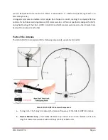
Attach the small 6 ½ inch Coupling Loop (c) 
to the Coupling Loop Attachment (j), located 
at  the  top  of  the  Telescoping  Mast,  by 
placing  the  threaded  hole  in  the  Coupling 
Loop  bracket  over  the  Coupling  Loop 
Attachment  stud  and  turning  the  Coupling 
Loop  Adjustment  (k)  knob  until  snug.    The 
UHF  connector  should  be  in  front  of  the 
Telescoping Mast and point down, as shown 
in the upper-left inset of Plate (3). 

5.


Extend the Telescoping Mast sections so that 
the Telescoping Mast is 24 inches in length. 

6.


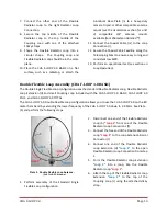
Connect  one  end  of  the  Flexible  Radiator 
Loop  (b)  to  the  left  Radiator  Loop 
Connection (f). 

Содержание CHA F-LOOP 3.0

Страница 1: ...CHA F LOOP 3 0 Page 1 HF Portable Loop Antenna 3 0 CHA F LOOP 3 0 Operator s Manual Nevada USA WWW CHAMELEONANTENNA COM VERSATILE DEPENDABLE STEALTH BUILT TO LAST...

Страница 2: ...9 Double Flexible Loop Assembly CHA F LOOP 3 0 BASIC 10 Flexible Booster Loop Assembly CHA F LOOP 3 0 TOTAL 11 Rigid Radiator Loop Assembly CHA F LOOP 3 0 PLUS 12 Power Compensator Installation 13 Lo...

Страница 3: ...real practical advantage of the small loop compared to a short vertical whip tuned against earth or a full sized vertical antenna is the loop s freedom from dependence on a ground plane and earth for...

Страница 4: ...cause you to mistune the antenna Antennas built by Chameleon AntennaTM are versatile dependable stealthy and built to last Please read this operator s manual so that you may maximize the utility you...

Страница 5: ...m Usable Frequency MUF Lowest Usable Frequency LUF and Optimal Working Frequency OWF The MUF is the frequency for which successful communications between two points is predicted on 50 of the days of i...

Страница 6: ...NVIS during field testing of the CHA F LOOP 3 0 both DX and NVIS contacts were made on the 30 meter ham band within minutes of each other Parts of the Antenna The CHA F LOOP 3 0 is comprised of the f...

Страница 7: ...diameter 146 inch length of shorted coaxial cable with UHF Plugs at both ends and is designed to increase CHA F LOOP 3 0 TOTAL performance in the 60 through 15 meter ham bands f Flexible Radiator Loo...

Страница 8: ...del p Rigid Radiator Loop Mounts The Rigid Radiator Loop Mounts are used to attach the Rigid Radiator Loop o to the Tuning Unit a q Telescoping Mast Stud The Telescoping Mast Stud is located on top of...

Страница 9: ...following steps to assemble the Standard Single Flexible Loop configuration 1 Select a location to setup the CHA F LOOP 3 0 BASIC antenna The location can be indoors or in an outdoors area protected...

Страница 10: ...gle Flexible Loop configuration uses the standard Flexible Radiator Loop Flexible Radiator Loop Extension d and small Coupling Loop included with the CHA F LOOP 3 0 BASIC CHA FLOOP 3 0 PLUS and CHA F...

Страница 11: ...he transmitter and observing the SWR meter If used indoors the location should also be reasonably away from switching power supplies Internet routers and other sources of electrical and electronic int...

Страница 12: ...the Rigid Radiator Loop Antenna see plate 6 1 Select a location to setup the CHA F LOOP 3 0 PLUS antenna The location can be indoors or in an outdoors area protected from the weather The location must...

Страница 13: ...tible antenna mounts available from Chameleon AntennaTM 9 Connect the Coaxial Cable Feedline m to the Loop Connection l 10 Secure the Coaxial Cable Feedline along the Telescoping Mast to ensure easy t...

Страница 14: ...antenna configuration Figure 1 Band Switch Label Table 2 shows the more precise frequency range for each antenna configuration and switch setting If the desired operating frequency is in both positio...

Страница 15: ...ky straps 5 If used un attach the Rigid Radiator Loop Re install the hardware in the Rigid Radiator Loop flanges so they do not get lost 6 Fully collapse Telescoping Mast 7 Remove Coupling Loop from t...

Страница 16: ...ible Booster Loop approximately 4 0 23 1 MHz 60 through 15 meter ham bands Power 25W intermittent duty cycle SSB telephony 10W continuous duty cycle CW AM FM RTTY and other digital modes Diameter 34 i...

Страница 17: ...ly any flat surface CHA SPIKE MOUNT The CHA SPIKE MOUNT is an innovative product built exclusively by the skilled machinists at Chameleon AntennaTM It is a precision fabricated heavy duty stainless st...

Страница 18: ...Portable Antenna Pioneer References 1 Silver H Ward editor 2013 2014 ARRL Handbook for Radio Communications 91st Edition American Radio Relay League Newington CT 2 1987 Tactical Single Channel Radio...

Отзывы: