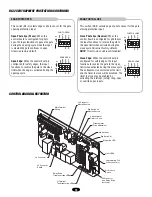
Chamberlain LiftMaster Professional SL585 Скачать руководство пользователя страница 1

C

O

NTR

O

LLER

 BO

ARD

GL

Serial #  ________________________
(located on electrical box cover)

Installation Date __________________

2 YEAR WARRANTY

MODELS SL585 AND SL595 ARE FOR VEHICULAR 

PASSAGE GATES ONLY AND ARE NOT INTENDED FOR 

PEDESTRIAN PASSAGE GATE USE

MODEL SL585

HEAVY DUTY SLIDE GATE OPERATOR

MODEL SL595

HEAVY DUTY, HARSH ENVIRONMENT

SLIDE GATE OPERATOR

Содержание LiftMaster Professional SL585

Страница 1: ...ox cover Installation Date__________________ 2 YEAR WARRANTY MODELS SL585 AND SL595 ARE FOR VEHICULAR PASSAGE GATES ONLY AND ARE NOT INTENDED FOR PEDESTRIAN PASSAGE GATE USE MODEL SL585 HEAVY DUTY SLI...

Страница 2: ...stall Vent Plug 14 UL325 Entrapment Protection 14 15 Control Board Illustration 15 Program Settings 16 Control Connection Diagrams 17 Radio Reciever 18 19 Accessory Wiring 19 20 Earth Ground Rod Insta...

Страница 3: ...Gate Width 45 ft 13 7 m Maximum V Track Gate Width 35 ft 10 7 m 1 HP Motor Maximum Gate Speed 12 sec 30 5 cm sec Maximum Gate Weight 1700 lbs 771 1 kg Maximum Cantilever Gate Width 35 ft 10 7 m Maximu...

Страница 4: ...eans of entrapment protection Both primary and secondary entrapment protection methods must be designed arranged or configured to protect against entrapments in both the open and close directions of g...

Страница 5: ...t be located at least six feet 6 away from any moving part of the gate and where the user is prevented from reaching over under around or through the gate to operate the controls Outdoor or easily acc...

Страница 6: ...es for Close Cycle 4 1 2 m Typical 4 1 2 m Typical Open Edge Photo Eyes for Open Cycle Run Twisted Wire from Loop to Operator STREET COMPLEX OR PARKING LOT Gate 1 Interrupt Safety Loop Photo eye for o...

Страница 7: ...both inside and outside of a vehicular horizontal slide gate Non contact sensors such as photo eyes must protect during both open and close gate cycles Injuries occur when people put their hands and a...

Страница 8: ...f the power disconnect should be visible and clearly labeled ALL power and control wiring MUST be run in separate conduit BEFORE installing power wiring or control stations be sure to follow all speci...

Страница 9: ...e 2 2 Locate electrical conduit as required prior to pouring concrete 3 Pour concrete pad 4 Secure operator Figure 3 to the concrete pad using four 1 2 concrete anchors not provided Figure 1 Figure 2...

Страница 10: ...o pouring concrete 3 Secure operator to posts using four 3 U bolts and hardware provided Figure 3 Figure 2 14 35 6 cm Min Ground Level Depth As Required By Local Codes or Below Frost Line 3 7 6 cm Out...

Страница 11: ...ain slack for every 10 3 1 m of chain length Do not overtighten chain NOTE ABOUT SOME TYPES OF CANTILEVER GATES With some cantilever gates over 20 6 1 m long you may need to add a brace along the leng...

Страница 12: ...ns inside the disconnect switch electrical box Refer to electrical wiring diagrams on pages 27 30 MANUAL DISCONNECT 115VOLT 1 PH USE COPPER CONDUCTO R ONLY 115VOLT 1 PH USE COPPER CONDUCTOR ONLY 115V...

Страница 13: ...y to adjust the sensor for correct alignment To do so please perform the following steps 1 The sensor must be centered over the magnet wheel Adjust with horizontal screws 2 The sensor must be level 3...

Страница 14: ...the gate is closing will have no effect Terminals 10 5 Obstruction While Closing Edge Photo Eye Input Edge Input See Programming Section on page 15 This input will reverse a closing gate to the open l...

Страница 15: ...he gate to the open limit when activated during the close cycle The entrapment is not cleared at the limit and the timer to close will be disabled The timer to close may be enabled by activating the i...

Страница 16: ...N SAVE TTC ON S1 RT LT SW SL RT LT SW SL 1 2 3 4 ON SAVE TTC ON S1 1 2 3 4 ON SAVE TTC ON S1 RT LT SW SL RT LT SW SL Factory Default TIMER TO CLOSE ENABLED SWING GATE SLIDE GATE TIMER TO CLOSE DISABLE...

Страница 17: ...guidelines presented throughout the manual Installation device instructions Always follow the instructions provided by the manufacturer when installing and adjusting any control device If these instru...

Страница 18: ...To prevent possible SERIOUS INJURY or DEATH from a moving gate or garage door ALWAYS keep remote controls out of reach of children NEVER permit children to operate or play with remote controls Activat...

Страница 19: ...eration is subject to the following two conditions 1 this device may not cause harmful interference and 2 this device must accept any interference received including interference that may cause undesi...

Страница 20: ...any additional surge protection MASTER SECOND SYSTEMS Dual Gate Communications The control board is capable of running the operator in a master or second mode depending on S4 switch setting Before in...

Страница 21: ...ground rod must be located within 3 feet from the gate operator Use the proper type earth ground rod for your local area The ground wire must be a single whole piece of wire Never splice two wires for...

Страница 22: ...pair of slide swing gate operator The design of this gate system balances the demands of speed during high traffic periods with security during low traffic periods Barrier gates typically have the fa...

Страница 23: ...rea Clean the operator as needed 6 It is suggested that while at the site voltage readings be taken at the operator Using a Digital Voltmeter verify that the incoming voltage to the operator it is wit...

Страница 24: ...uction the clutch will slip 1 Loosen set screws of torque adjustment nut on the gear reducer output shaft 2 Back off torque nut until there is very little tension on the Belleville washers 3 Tighten t...

Страница 25: ...ult Control Input 6 Loss of communications Removal of between master and problem second during run mode On No Motor not learned Completion Flash of Motor Learn Routine Hard inputs include open overrid...

Страница 26: ...he operator This voltage should be within 5 of 24Vac If the high voltage power is good and the low voltage power is bad check to make sure the circuit fuse is not tripped and that the correct primary...

Страница 27: ...The brake should disengage when the contactor activates and engage when the contactor releases Both LEDs will indicate the activation of entrapment protection devices on terminals TB1 9 and TB1 10 on...

Страница 28: ...R AT O R S H E AT E R W I R I N G D I A G R A M F O R 2 0 8 2 3 0 4 6 0 A N D 5 7 5 V O P E R AT O R S HEATER REPLACEMENT PARTS PART NUMBER DESCRIPTION QTY 21 15453 1 Transformer 100VA with 3 2A fuse...

Страница 29: ...B A A1 A2 A1 A2 RPM SENSOR GL CONTROL BOARD 24VAC IN 24VAC COMMON SOFT OPEN NC B LIMIT CONTACTOR B A LIMIT CONTACTOR A RPM IN RPM SUPPLY RPM GND RADIO COMMAND SHADOW 24VDC CLOSE STOP SOFT OPEN HARD OP...

Страница 30: ...B NC C YEL BLK Y BK GY TB2 BL Y PU GY BL Y PU 1 3 8 5 4 2 OL BK BK BK BK BL BK BL BK 115V BRAKE SOLENOID 115V CONNECTION 230V BRAKE SOLENOID 208 230V CONNECTION BL BK BL BK 4 5 2 3 8 1 LOOP WIRING TB...

Страница 31: ...RD WH PU P W Y BK GN Y BK Y BK WH BRN BRN OR GN GY OR BK WH RD BK BK BL YE GY BRN GY BRN OR Y BK GN Y BK YE YE BL BL BRN PU OR BL BL BK BK YE YE YE RD RD L3 BK BK FACTORY INSTALLED RADIO 40 32351G 3...

Страница 32: ...32 T H R E E P H A S E S C H E M AT I C...

Страница 33: ...0 Alarm kit Complete with Alarm spacer and faston K9 K75 18493 Chain guide kit K10 653509 Optional diagonal brace kit NOT SHOWN 71 6532449 Heater kits Optional 115 575V Operators 71 6532448 Heater kit...

Страница 34: ...5 34842 10 2 1 K1 71 B120 71 B240 71 B575 K2 K75 10177 6 K4 K75 34824 4 3 4 3 K3 K75 34828 K6 K75 34790 K7 K75 34791 K8 K29 32410 8 K9 K75 18493 K10 653509 I L L U S T R AT E D P A R T S M O D E L 5 8...

Страница 35: ...larm kit Complete with Alarm spacer and faston K7 K75 18493 Chain guide kit NOT SHOWN 71 6532449 Heater kits Optional 115 575V Operators 71 6532448 Heater kits Optional 208 230 460V Operators K50 1842...

Страница 36: ...AT E D P A R T S M O D E L 5 9 5 3 6 12 13 4 5 6 1 2 7 8 9 11 K3 K75 12858 K1 71 B120 71 B240 71 B575 K2 K75 18618 K4 K75 18620 K6 K29 32410 K5 K72 18615 19 18 18 16 17 15 10 14 K7 K75 18493 312HM Rec...

Страница 37: ...erload 10 AMP SL585 50 11 SL595 50 11 SL585 150 21 SL595 150 21 25 2015 Overload 15 AMP SL585 100 11 SL595 100 11 25 2025 Overload 25 AMP SL585 150 11 SL595 150 11 Non stocked item Please allow additi...

Страница 38: ...9 m Maximum Range 24V ac dc SENSING EDGES MODEL DESCRIPTION VOLTAGE G65MG0204 Miller MG020 2 wire electric edge for gates Sensitized on three sides 24V ac dc Requires mounting channel 4 1 2 m long G65...

Страница 39: ...39 N O T E S...

Страница 40: ...ation may not apply to you THIS LIMITED WARRANTY DOES NOT COVER NON DEFECT DAMAGE DAMAGE CAUSED BY IMPROPER INSTALLATION OPERATION OR CARE INCLUDING BUT NOT LIMITED TO ABUSE MISUSE FAILURE TO PROVIDE...

Отзывы: