Challenger_ASFK1_Instructions_Rev01
ASFK1
Gateway Hub
User Manual
1. Introduction
The ASFK1 Gateway is a member of the Smart Force series and is fully
compatible with any Smart Force enabled devices. It can remotely
control and monitor remote enabled devices. Whether onsite or logged
in through the internet, you will always have access to control and
monitor your control system. With this system you can achieve a better
control of your home security to make your life safer and easier than
ever.
2. Appearance
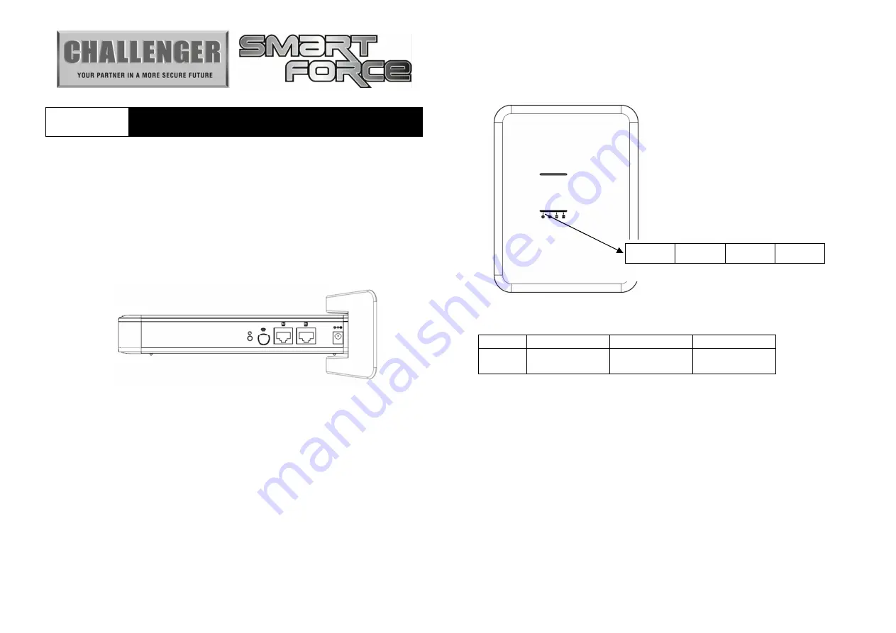
Figure 1 ASFK1 Gateway Hub
2.1 Sockets
DC Jack: DC power voltage 9V, current 2A.
RJ-45 socket: ASFK1 has an Ethernet hub function and is equipped
with two linked RJ-45 sockets.
2.2 Buttons
ASFK1 has two buttons: One reset button and a connection button
(next to the RJ-45 socket).
■
Reset Button:
This button will reboot the system. The user can press this button
when the system has stopped working.
Note: ASFK1 is equipped with internal battery power, which will be
automatically switched on when DC power is disconnected.
■
Connection Button:
‧
Manually enable the learn function:
Press the connection button once after the system is powered on.
‧
Manually cancel the learn function:
Press the connection button once when the system is in learn
mode.
2.3. LED
Figure 2 ASFK1 Front View
Definition of LED:
LED1
Power
LED2
Connection
LED3
Network 1
LED (RJ45)
LED4
Network 2
LED (RJ45)
2.3.1 Power LED
Green light: The power is on.
Red light: Flashing writing data.
Red light flashes every 5 seconds: The system time is not
synchronized after boot up.
2.3.2. Connection LED
Green light: Open VPN has successfully connected to the server.
Red light: The DHCP function is enabled but could not obtain IP
information.
Red and green light flashes: The firmware is being upgraded.
Green light flashes every of 0.5 seconds: The system is in learning
mode.
Green light flashes every 2 seconds: The system has successfully
added other radio devices.
LED1
LED2
LED3
LED4


