


CET Electric Technology
78
+8
RW
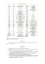
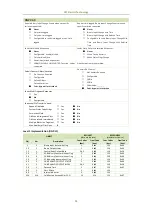
Parameter #1
1
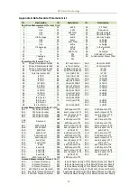
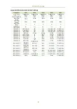
UINT16 Please refer to Appendices
A and B for a complete list
of the Data Recorder
Parameters and the default
configuration for each DR,
respectively.
+9
RW
Parameter #2
1
UINT16
+10
RW
Parameter #3
1
UINT16
…
RW
…
UINT16
+23
RW
Parameter #16
1
UINT16
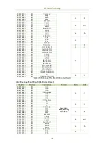
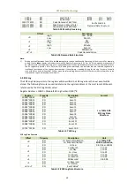
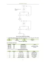
Table 5-43 DR Setup Parameter Data Structure
Notes:
1)
Changing any of these Data Recorder setup registers will reset the Data Recorder.
2)
Recording Offset can be used to delay the recording by a fixed amount of time from the Recording Interval. For example,
if the Recording Interval is set to 3600 (hourly) and the Recording Offset is set to 300 (5 minutes), the recording will take
place at 5 minutes after the hour every hour, i.e. 00:05, 01:05, 02:05, etc. Thus Recording Offset < Recording Interval.
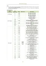
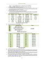
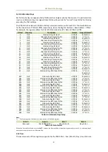
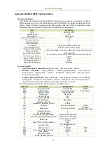
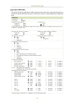
5.12 TOU Setup
5.12.1 Basic
Register
Property
Description
Format
Range/Option
7000
RO
Current Tariff
1
UINT16
0=T1, 1=T2, 2=T3, 3=T4
4=T5, 5=T6, 6=T7, 7=T8
7001
RO
Current Season
UINT16
0 to 11
(Season #1 to #12)
7002
RO
Current Period
UINT16
0 to 11
(Period #1 to #12)
7003
RO
Current Daily Profile No.
UINT16
0 to 19
(Daily Profile #1 to #20)
7004
RO
Current Day Type
UINT16
0=Weekday1
1=Weekday2
2=Weekday3
3= Alternate Day
7005
RO
Current TOU No.
UINT16
0=TOU #1
1=TOU #2
7006
RW
TOU Switch Time
UINT32
See Note (1)
7008
WO
Switch TOU Manually
UINT16
Write 0xFF00 to manually
switch the TOU schedules
7009
RW
Sunday Setup
UINT16
0=Weekday1*
1=Weekday2
2=Weekday3
7010
RW
Monday Setup
UINT16
7011
RW
Tuesday Setup
UINT16
7012
RW
Wednesday Setup
UINT16
7013
RW
Thursday Setup
UINT16
7014
RW
Friday Setup
UINT16
7015
RW
Saturday Setup
UINT16
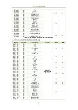
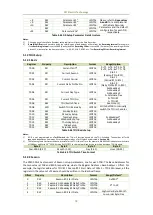
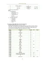
Table 5-44 TOU Basic Setup
Notes:
1)
If DI1 is not programmed as a Tariff Switch, the TOU will function based on the TOU Schedule. The number of Tariffs
supported depends on how many DIs are programmed as a Tariff Switch as indicated in Section 4.6.
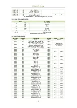
2)
The following table illustrates the data structure for the TOU Switch Time. For example, 0x1003140C indicates a switch time
of 12:00pm on March 20
th
, 2016. Writing 0xFFFFFFFF to this register disables the switching between TOU Schedule.
Byte 3
Byte 2
Byte 1
Byte 0
Year-2000 (0-37)
Month (1-12)
Day (1-31)
Hour (00-23)
Table 5-45 TOU Switch Time Format
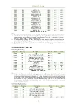
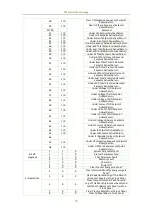
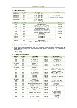
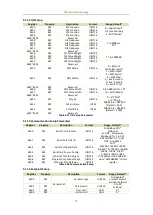
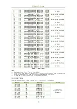
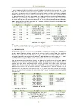
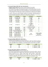
5.12.2 Season
The PMC-53A-E has two sets of Season setup parameters, one for each TOU. The Base Addresses for
the two sets are 7100 and 8100, respectively, where the Register Address = Base A Offset. For
example, the register address for TOU #1’s Season #2’s Start Date is 7100+4 = 7104. Moreover, all the
registers in the same set of Season should be written in the identical frame.
Offset
Property
Description
Format
Range/Default*
0
RW
Season #1: Start Date
UINT16
0x0101*
1
RW
Season #1: Weekday#1 Daily Profile
UINT16
0* to 19
2
RW
Season #1: Weekday#2 Daily Profile
UINT16
3
RW
Season #1: Weekday#3 Daily Profile
UINT16
4
RW
Season #2: Start Date
UINT16
High-order Byte: Month
Low-order Byte: Day


