Ceiec Electric Technology
15
Pin 1: Orange-White
Pin 1: Orange-White
Pin 2: Orange
Pin 2: Orange
Pin 3: Green-White
Pin 3: Green-White
Pin 4: Blue
Pin 4: Blue
Pin 5: Blue-White
Pin 5: Blue-White
Pin 6: Green
Pin 6: Green
Pin 7: Brown-White
Pin 7: Brown-White
Pin 8: Brown
Pin 8: Brown
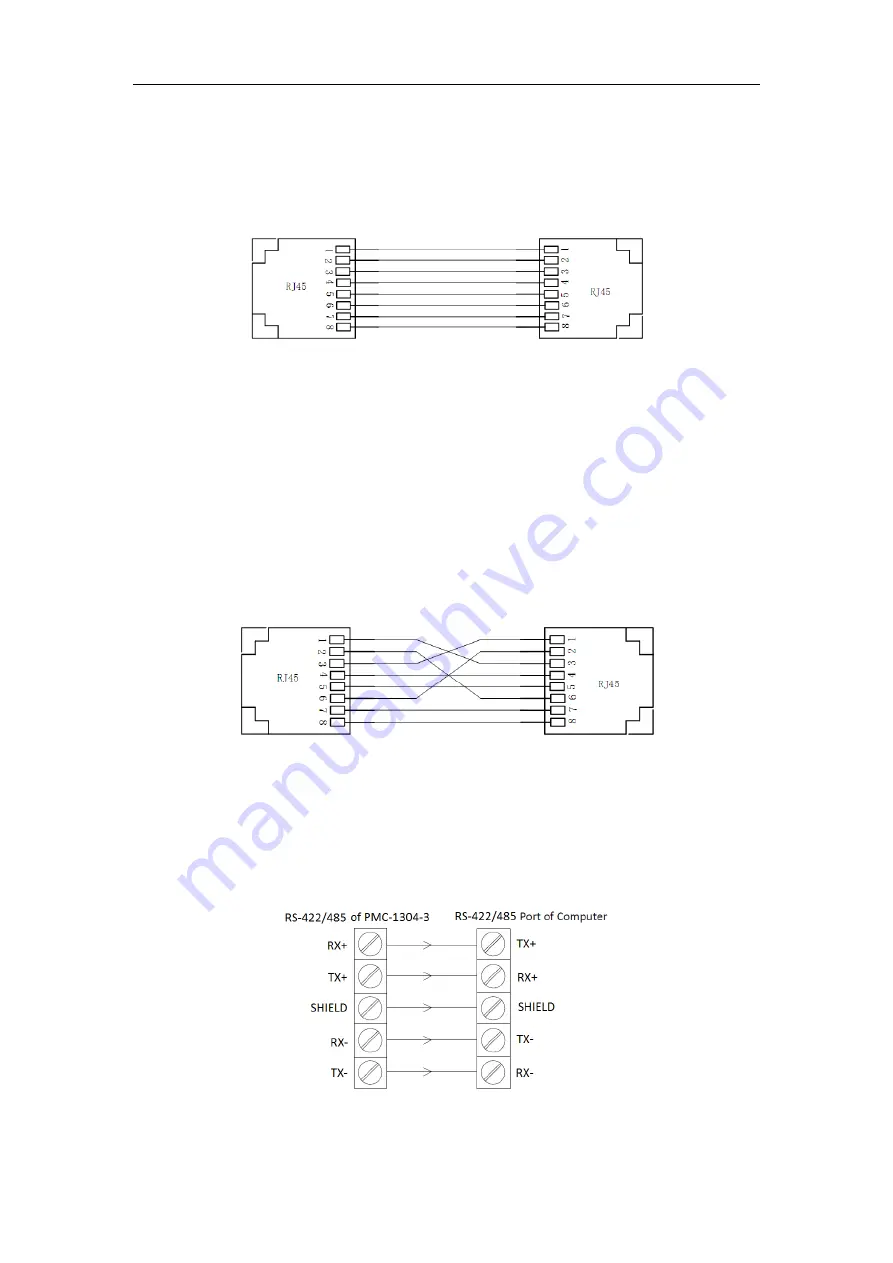
Figure 2-8 Straight through Connection
2.6.2 Cross-over Connection
A cross-over RJ45 cable should be used if the PMC-1304-3 is connected directly to a PC’s Ethernet port.
The following figure illustrates the definition of an 8-pin RJ45 cross-over cable. The color-coded
wires should be connected to the pins of the RJ45 connector as follows:
Pin 1: Orange-White
Pin 3: Green-White
Pin 2: Orange
Pin 6: Green
Pin 3: Green-White
Pin 1: Orange-White
Pin 4: Blue
Pin 4: Blue
Pin 5: Blue-White
Pin 5: Blue-White
Pin 6: Green
Pin 2: Orange
Pin 7: Brown-White
Pin 7: Brown-White
Pin 8: Brown
Pin 8: Brown
Figure 2-9 Cross-over Connection
2.7 Serial Port Wiring
2.7.1 P3 (RS-422/485) Wiring
The P3 port of PMC-1304-3 can be used as a RS-485 or a RS-422 port. The following figure illustrates
the RS-422/485 communications connections on the PMC-1304-3:
Table 2-3 RS-422/485 Connection


