background image

Содержание 177 SERIES

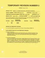
Страница 1: ...REPRINT MODEL 177 SERIES 1968 thru 1978 SERVICE MANUAL 4 OCTOBER 1995 D841 8 13 THIS REPRINT INCORPORATES CHANGE 8 DATED 2 OCTOBER 1995 ...

Страница 2: ... Member of GAMA FAA APPROVAL HAS BEEN OBTAINED ON TECHNICAL DATA IN THIS PUBLICATION THAT AFFECTS AIRPLANE TYPE DESIGN THIS REPRINT INCORPORATES CHANGE 8 DATED 2 OCTOBER 1995 CESSNA AIJCRAFT COMPANY I JULY 1 970 WICHITA KANSAS USA D841 8 13 CHANGE 8 2 OCTOBER 1995 RGI 50 12 00 ...

Страница 3: ... inclusion of the Temporary Revision into the manual Insert the new pages into the publication at the appropriate locations and remove and discard the superseded pages 2 For Aerofiche Publications draw a line with permanent red ink marker through any aerofiche frame page affected by the Temporary Revision This will be a visual identifier that the information on the frame page isno longer valid and...

Страница 4: ...f the Temporary Revision into the manual Insert the new pages into the publication at the appropriate locations and remove and discard the superseded pages 2 For Aerofiche Publications draw a line with permanent red ink marker through any aerofiche frame page affected by the Temporary Revision This will be a visual identifier that the information on the frame page isno longer valid and the Tempora...

Страница 5: ...em Operational Test FILING INSTRUCTIONS FOR THIS TEMPORARY REVISION 1 For Paper Publications file this cover sheet behind the publication s title page to identify the inclusion of the Temporary Revision into the manual Insert the new pages into the publication at the appropriate locations and remove and discard the superseded pages 2 For Aerofiche Publications draw a line with permanent red ink ma...

Страница 6: ...blications File this cover sheet behind the publication s title page to identify the inclusion of the Temporary Revision into the manual Insert the new pages into the publication at the appropriate locations Draw a line with a permanent red ink marker through any superceded information For Aerofiche Publications Draw a line through any aerofiche frame page affected by the Temporary Revision with a...

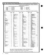
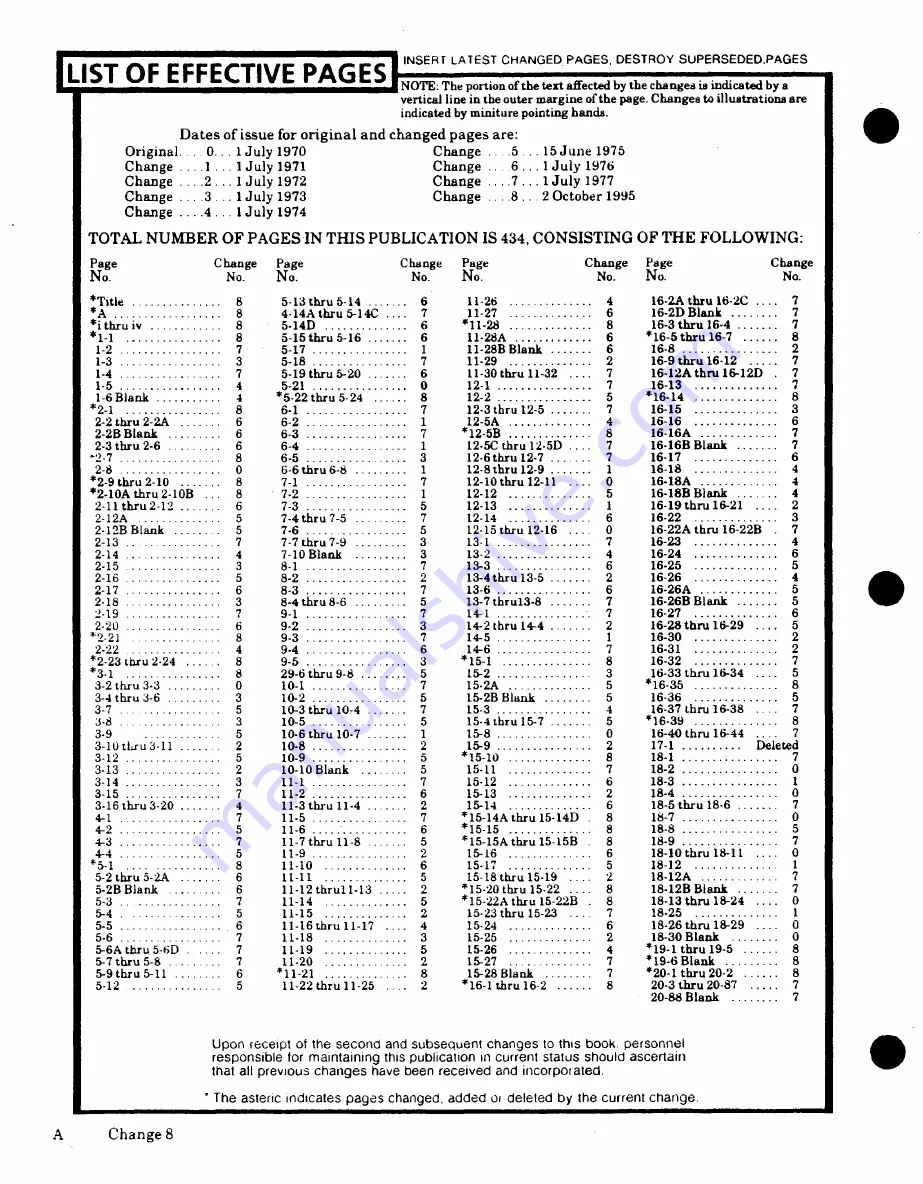
Страница 7: ... 10 Blank 3 13 2 4 46 2 15 13 3 6 16 25 2 16 5 8 2 2 13 4thru 135 2 16 26BBl 4 2 17 6 3 7 13 6 6 16 26A 5 2 18 3 8 4 thru8 6 5 13 7 thru3 8 7 16 26BBlank 5 2 19 7 thru 7 16 2 6 2 20 6 9 2 3 3 14 2thru4 2 16 28thru 29 3 21 8 9 3 5 1 16 30 2 2 22 4 9 4 6 7 16 31 2 2 273 1 ru 224 7 3 1 8 29 6 thru 9 8 B n 3 16 33 thru 16 34 3 2 thru 3 3 0 10 1 7 15 2A 5 1635 8 3 thru 6 3 10 2 5 1 2BBlnk 5 16 36 5 3 7...

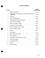
Страница 8: ...LERON CONTROL SYSTEM 1F4 6 1 7 WING FLAP CONTROL SYSTEM 1F18 7 1 8 STABILATOR CONTROL SYSTEM 1G9 8 1 9 STABILATOR TRIM CONTROL SYSTEM 1G21 9 1 10 RUDDER CONTROL SYSTEM lHll 10 1 11 ENGINE 112 11 1 12 FUEL SYSTEM 1 17 12 1 13 PROPELLER AND GOVERNOR 1K19 13 1 14 UTILITY SYSTEMS 1L9 14 1 15 INSTRUMENT AND INSTRUMENT SYSTEMS 2A2 15 1 16 ELECTRICAL SYSTEMS 2B15 16 1 18 STRUCTURAL REPAIR 2E5 18 1 19 PAI...

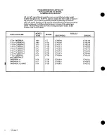
Страница 9: ...e provides a listing of popular name model number and serial number MODEL SERIALS POPULAR NAME M ODEL POPULAR NAME YEAR MODEL BEGINNING ENDING 177 or CARDINAL 1968 177 17700001 17701164 177A or CARDINAL 1969 177A 17701165 17701370 177B or CARDINAL 1970 177B 17701371 17701530 177B or CARDINAL 1971 177B 17701531 17701633 177B or CARDINAL 1972 177B 17701634 17701773 177B or CARDINAL 1973 177B 1770177...

Страница 10: ...or some of the various suppliers equipment items Suppliers publications are updated supplemented and specifically amended by supplier issued revisions and service information which may be reissued by Cessna thereby automatically amending this publication and is communicated to the field through Cessna Authorized Service Stations and or Cessna subscription service WARNING ALL INSPECTION INTERVALS R...

Страница 11: ...new products SUPPLEMENTAL TYPE CERTIFICATE INSTALLATIONS Inspection maintenance and parts required for STC installations are not included in this manual When an STC installation is incorporated on the aircraft those portions of the aircraft affected by the installation must be inspected in accordance with the inspection program published by the owner of he STC Since STC installations may change sy...

Страница 12: ...s fuel bay area in each wing The fixed tricycle land that are considerably different from those listed ing gear consists oftubular spring steel main gear struts and a steerable nose gear with an air hydrau 1 5 STATIONS A station diagram is shown in fig lic fluid shock strut Standard four place seating ure 1 2 to assist in locating equipment when a written consists of two individual front seats and...

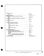
Страница 13: ...Engine Data 1968 Model 177 Cardinal LYCOMING 0 320 Series 1969 Model 177A Cardinal and on LYCOMING 0 360 Series PROPELLER 1968 and 1969 Models 177 177A Cardinals 76 McCauley Fixed Pitch 1970 Model 177B Cardinal and on 76 McCauley Constant Speed MAIN WHEEL TIRES 1968 Models 6 00x6 4 ply rating 1969 and on 6 00x6 6 ply rating Pressure 30 psi NOSE WHEEL TIRE Standard 5 00x5 4 ply rating Pressure Seri...

Страница 14: ...01164 Up 2 1 Down 7 1 Serial 17701165 thru 17701370 Up 6 2 0 Down 12 0 2 Serial 17701371 and on Up 5 1 Down 13 1 PRINCIPAL DIMENSIONS Wing Span Conventional Wing Tip 35 7 1 2 Wing Span Conical Camber Wing Tip 35 6 Wing Span Conical Camber with Strobe Lights 35 8 Tail Span 11 10 Length 27 3 Fin Height Maximum with Nose Gear Depressed and Flashing Beacon Installed on Fin 8 7 Track Width 8 3 1 2 BATT...

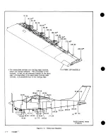
Страница 15: ...e canted outboard The remainder of the stations as well as the stations forward of the main spar corresponding to the asterisked trailing edge stations are perpendicular to the leading edge 123 53 147 54 59 00 123 164 53 t 23so 263 00 r 7 87 75 77 155 50 277 00 54 00J 68 66 100 00 132 00 175 50 64 90 111 75 140 50 BEGINNING WITH 17701371 Figure 1 2 Reference Stations 1 4 Change 7 ...

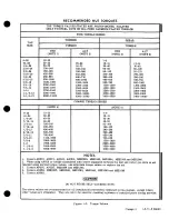
Страница 16: ...E 5 8 32 12 15 7 9 10 24 20 25 12 15 1 4 20 40 50 25 30 5 16 18 80 90 48 55 3 8 16 160 185 95 100 7 16 14 235 255 140 155 1 2 13 400 480 240 290 9 16 12 500 700 300 420 5 8 11 700 900 420 540 3 4 10 1150 1600 700 950 7 8 9 2200 3000 1300 1800 1 8 3700 5000 2200 3000 1 1 8 8 5500 6500 3300 4000 1 1 4 8 6500 8000 4000 5000 NOTES 1 Covers AN310 AN315 AN345 AN363 MS20365 MS21042 MS21044 MS21045 and MS...

Страница 17: ...1A23 2 6 Propeller 1B5 2 10B Fuel 1 A23 2 6 Wheels 1B5 2 10B Fuel Drains A23 2 6 LUBRICATION 1B5 2 10B Carburetor Drain Plug Inspection 1A23 2 6 Tachometer Drive Shaft B5 2 10B Engine Oil 1A23 2 6 Wheel Bearings 1B5 2 10B Induction Air Filter 1A24 2 7 Aileron Rod End Bearings 1B5 2 10B Vacuum System Filter 1B1 2 8 Wing Flap Actuator 1B5 2 10B Battery B1 2 8 INSPECTION 1B13 2 17 2 1 GROUND HANDLING...

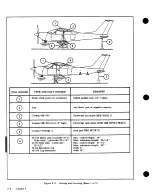
Страница 18: ... 576 41 1 2 high Universal jack stand FOR USE WITH ITEM 2 Cessna 1700129 1 Jack pad SEE NOTE 2 2 170 Basic jack includes 2 71 Min closed height 34 Slide tube Liftstroke 22 1 2 Max extension height 56 1 2 2 70 Slide tube Liftstroke Min closed height 57 1 2 22 1 2 Max extension height 80 2 64 Extension cap Adds 4 2 109 Leg extension Adds 12 Figure 2 2 Jacking and Leveling Sheet 1 of 2 2 2 Change 6 ...

Страница 19: ...outboard of main wheel Pad at top of jack should be placed at junction of main wing spar and wing rib 2 Raise aircraft tail and attach tail stand to tie down fitting BE SURE the tail stand weighs enough to keep the tail down under all conditions and that it is strong enough to support any weight that may be placed upon it 3 Operate jacks evenly until desired height is reached 4 The individual stru...

Страница 20: ...covers ponding points is used to level the aircraft laterally installed to prevent entry of foreign material After 30 days aircraft should be flown for 30 minutes or 2 6 PARKING Parking precautions depend prin ground run up until oil has re ched operating temper cipally on local conditions As a general precaution ature set parking brakes or chock the wheels and installthe controls lock In severe w...

Страница 21: ...acard from propeller NOTE e Remove materials used to cover openings f Remove clean and gap spark plugs Refer to The preservative oil must be Lubricating Oil Section 11 Contact and Volatile Corrosion Inhibited g While spark plugs are removed rotate propeller MIL L 46002 Grade 1 or equivalent The several revolutions to clear excess rust preventive following oils are approved for spraying oil from cy...

Страница 22: ... 6 months respray the cylinder inteors ly cover interior surfaces of cylinders with corrosion preventive mixture g Install lower spark plugs or install solid plugs NOTE and install dehydrator plugs in upper spark plug holes Be sure that dehydrator plugs are blue in color when installed Before spraying inspect the interior of one h Cover spark plug lead terminals with shipping cylinder for corrosio...

Страница 23: ...ed by the use of straight through the oil dipstick access door Remove drain mineral oil The aircraft is delivered from plugs and open strainer drain at the intervals speci Cessna with a Corrosion Preventive Aircraft fied in figure 2 3 to drain water and sediment from Engine Oil MIL C 6529 Type II RUST the fuel system BAN If oil must be added during the first 25 hours of operation use only aviation...

Страница 24: ...by operating conditions Some operators prefer to hold spare induction air filters at their home base of Refer to figure 2 3 for intervals for changing operation so that a clean filter is always readily avail oil and filter elements able for use Under extremely dusty conditions daily servicing of the filter is recommended NOTE NOTE To minimize loss of oil through the breather fill to specified oil ...

Страница 25: ... gear aged filter may have sharp or broken shock strut requires periodic checking to ensure that edges in the filtering panels which would the strut is filled with hydraulic fluid and is inflated allow unfiltered air to enter the induction to the correct air pressure To service shock system Any filter that appears doubtful strut proceed as follows should have a new filter installed a Remove valve ...

Страница 26: ...n all hydraulic system of entrapped air whenever there is a spongy fluid from dampener Work dampener piston rod back response to the brake pedals Refer to Section 5 for and forth and ascertain that all fluid has drained filling and bleeding the brake system from dampener c After all fluid is drained move shimmy dampen 2 29 CLEANING er piston to end of barrel opposite filler hole d With dampener an...

Страница 27: ...urface but extreme NOTE care must be exercised to prevent scratching the surface d On acrylic windshields and windows only if soils Utilization of the following techniques will which cannot be removed by a mild detergent remain help minimize windshield and window crazing Type II aliphatic naphtha applied with a soft cloth may be used as a cleaning solvent Be sure to frequently re a Keep all surfac...

Страница 28: ...sion of these areas device to clean polish or wax surfaces 2 34 ALUMINUM SURFACES The aluminum sur 2 32 INTERIOR TRIM The instrument panel faces require a minimum of care but should never plastic trim and control knobs need only be wiped be neglected The aircraft may be washed with clean off with a damp cloth Oil and grease on the control water to remove dirt and may be washed with non wheel and c...

Страница 29: ...e detergent used according move clean and lubricate jack screw whenever actu to the manufacturer s instructions ator slippage is experienced If lubrication is re e Oily spots and stains may be cleaned with house quired proceed as follows hold spot removers used sparingly Before using a Gain access to actuator by removing appro any solvent read the instructions on the container priate inspection pl...

Страница 30: ... 11 Figure 2 3 Servicing Sheet 1 of 4 Change 6 2 11 hne6 21 ...

Страница 31: ...ice Bulletins for further information SPECIFIED AVIATION GRADE OIL AVERAGE AMBIENT TEMPERATURE F OIL GRADE MAXIMUM OIL INLET TEMPERATURE 0 10 20 300 40 500 60 70 80 90 F SAE 40 OR SAE 50 245 I S SAE 40 245 SAE 40 OR SAE 30 225 SAE30 2100 NOTE The overlap of oil grades is based on a mid range of ambient ground temperatures vs maximum oil inlet temperature Aviation Grade ashless dispersant oil confo...

Страница 32: ... 22 for details FIRST 25 HOURS 19 ENGINE OIL SYSTEM Refill with straight mineral oil non detergent and use until a total of 50 hours has accumulated or oil consumption has stabilized then change to ashless dispersant oil 50 HOURS 17 INDUCTION AIR FILTER Clean filter per paragraph 2 22 Replace as required 6 BATTERY Check electrolyte level and clean battery compartment each 50 hours or each 30 days ...

Страница 33: ... RELIEF VALVE FILTER Change each 1000 hours or to coincide with engine overhauls 9 BRAKE MASTER CYLINDERS Check fluid level and fill as required with hydraulic fluid Refer to paragraph 2 28 for details 18 FUEL RESERVOIR TANK Remove plug and drain water and sediment Reinstall plug and safety Refer to paragraph 2 19 for details 500 HOURS VACUUM SYSTEM CENTRAL AIR FILTER Replace every 500 hours AS RE...

Страница 34: ...ese specifications LUBRICANTS PG SS G 659 1 POWDERED GRAPHITE GR MIL G 81322A GENERAL PURPOSE GREASE GH MIL G 23827A AIRCRAFT AND INSTRUMENT GREASE GL MIL G 21164C HIGH AND LOW TEMPERATURE GREASE OG MIL L 7870A GENERAL PURPOSE OIL PL VV P 236 PETROLATUM GS MIL S 8660 DC4 DOW CORNING GP NO 10 WEIGHT NON DETERGENT OIL SHIMMY DAMPENER PL PIVOTS BATTERY TERMINALS REFER TO PARA GRAPH 2 42 GR STEERING S...

Страница 35: ...UMN STABILATOR TRIM 0 XTAB ACTUATOR e9 ALSO REFER TO INSPECTION GL A fir f MCHART IN THIS SECTION AND s go o TO SECTION 9 OF THIS MANUAL PG k GR NEEDLE BEARINGS ALL PIANO NEEDLE HINGES BEARINGS R AILERON BELLCRANKS SCREW JACK THREADS t FLAP BELLCRANKS rG I AND DRIVE PULLEYS t A ALSO REFER TO PARAGRAPH 2 44 ELECTRIC FLAP DRIVE MECHANISM Figure 2 4 Lubrication Sheet 2 of 3 Change 3 2 15 ...

Страница 36: ... ends Oilite bearings pivot and hinge points and any other friction point obviously needing lubrication with general pur pose oil every 1000 hours or oftener if required Paralfin wax rubbed on seat rails will ease sliding the seats fore and aft Lubricate door latching mechanism with MIL G 81322A general purpose grease applied sparingly to friction points every 1000 hours or oftener if binding occu...

Страница 37: ...re continuous airworthiness c An inspection conducted at 200 hour intervals would likewise include the 50 hour items and 100 hour items in addition to those at EACH 200 HOURS d The numbers appearing in the SPECIAL INSPECTION ITEMS column refer to data listed at the end of the inspection charts These items should be checked at each inspection interval to insure that applicable servicing and inspect...

Страница 38: ... CRITICAL AREAS for correct torque in accordance with torque values given in the chart in Section 1 when installed or when visual inspection indicates the need for a torque check NOTE Torque values listed in Section 1 are derived from oil free cadmium plated threads and are recommended for all installation procedures contained in this book except where other values are stipulated They are not to b...

Страница 39: ...to Section 11 of this Manual 4 Engine response to changes in power 5 Any unusual engine noises 6 Fuel selector and or shut off valve operate engine s on each tank or cell position and OFF position long enough to ensure shut off and or selector valve functions properly 7 Idling speed and mixture proper idle cut off 8 Alternator and ammeter 9 Suction gage 10 Fuel flow indicator If equiped I After th...

Страница 40: ...Oil cooler 3 Induction air filter 2 4 Induction air box air valves doors and controls 5 Cold and hot air hoses 6 Engine baffles 7 Cylinders rocker box covers and push rod housings 8 Crankcase oil sump accessory section and front crankshaft seal 9 Hoses metal lines and fittings 3 10 Ignition and exhaust systems 4 11 Ignition harness 12 Spark plugs 13 Compression check 14 Crankcase and vacuum system...

Страница 41: ...ts caps and placards 2 Fuel strainer screen and bowl 3 Fuel reservoir 4 Fuel bays sump drains and fuel line drains 5 Drain fuel and check bay interior attachment and outlet screens 6 Fuel vent valves 7 Fuel vent line drain 8 Fuel selector valve and placards 9 Fuel shutoff valve and placards 10 Auxiliary fuel pump 11 Engine driven fuel pump 12 Fuel vent line drain plug 13 Engine primer 14 Perform a...

Страница 42: ...struments and markings 9 Gyros central air filter 10 Magnetic compass compensation 11 Instrument wiring and plumbing 12 Instrument panel shock mounts ground straps cover decals and labelii 13 Defrosting heating and ventilating systems and controls 14 Cabin upholstery trim sunvisors and ash trays 15 Area beneath floor lines hoses wires and control cables 16 Lights switches circuit breakers fuses an...

Страница 43: ...re ol control surfaces 13 Stabilizer balance weight attachment 18 14 Flap actuator jack screw threads 14 15 Aileron rod end bearing inspection 19 SPECIAL INSPECTION ITEMS 1 First 25 hours refill with straight mineral oil non detergent and use until a total of 50 hours have accumulated or oil consumption has stabilized then change to ashless dispersant oil Change oil each 50 hours if the engine is ...

Страница 44: ...ften if operated under prevailing wet or dusty conditions 10 Replace each 500 hours 11 Check electrolyte level and clean battery compartment each 50 hours or each 30 days 12 Refer to Section 16 of this Manual for details 13 Lubrication of the actuatbr is required each 1000 hours and or 3 years whichever comes first Refer to figure 2 4 for grease specification Refer to Section 9 of this Manual for ...

Страница 45: ...d from page 2 24 21 Fuel quantity indicating system operational test is required every 12 months Refer to Section 15 for detailed accomplishment instructions Temporary Revision Number 4 7 October 2002 2002 Cessna Aircraft Company 2 24A ...

Страница 46: ...ablished by an outside supplier on their product C Inaddition to these time limits the components listed herein are also inspected at regular time intervals set forth in the Inspection Charts and may require overhaul replacement before the time limit isreached based on service usage and inspection results 2 Cessna Established Replacement Time Limits A The following component time limits have been ...

Страница 47: ...r occurs first Note 10 Landing and Taxi Light Switch 5 years or Landing Light Switch Note 11 Aircraft serials 17701974 thru 17702313 Landing and Taxi Light Switch Aircraft serials 17702314 thru 17702672 Landing Light Switch Aircraft serials 17702673 thru 17702752 3 Supplier Established Replacement Time Limits A The following component time limits have been established by reproduced as follows Tabl...

Страница 48: ...for replacement and overhaul information Note 9 The air filter may be cleaned refer to Section 2 of this service manual for servicing instructions For airplanes equipped with an air filter manufactured by Donaldson refer to Donaldson Aircraft Filters Service Instructions P46 9075 for detailed servicing instructions The address for Donaldson Aircraft Filters is Customer Service 115 E Steels Corners...

Страница 49: ... THIS PAGE INTENTIONALLY LEFT BLANK D841 8 13 Temporary Revision Number 6 Janl5 2008 Cessna Aircraft Company 2 28 ...

Страница 50: ...damage is exten sive However certain repairs as prescribed in the fol J z WINDSHIELD AND WINDOWS lowing paragraphs can be made successfully without removing damaged part from aircraft Three types of 3 3 DESCRIPTION The windshield and windows are temporary repairs for cracked plastic are possible No single piece acrylic plastic panels set in sealing strips repairs of any kind are recommended on hig...

Страница 51: ...onstantly over damaged area soft clean dry cloth or imitation chamois until cloudy appearance disappears A 2000 foot per minute surface speed is recommended to prevent 3 8 CRACKS Refer to figure 3 1 overheating and distortion Example 750 rpm a When a crack appears drill a hole at end of polishing machine with a 10 inch buffing bonnet crack to prevent further spreading Hole should be approximately ...

Страница 52: ...e ap 4 dows when felt sealing strip 4 is used 1 E 1 Outer Retainer 5 Inner Retainer 1 2 Windshield 6 Cabin Top Skin 3 Cowl Deck 7 Door Post 4 Felt Seal 8 Window TYPICAL METHODS OF RETAINING FIXED WINDOWS Figure 3 2 Windshield and Fixed Window Installation 3 3 ...

Страница 53: ...cessary If not previously removed top retainer may be re 2 Drill out rivets around edge of door in the moved if necessary Starting at upper corner and area of window gradually working windshield into position is recom 3 Pull window out through top of door mended 4 Reverse preceding steps for installation Apply sealing strips and an adequate coating of seal NOTE ing compound to all edges of window ...

Страница 54: ... a TI B 4 C BEGINNING WITH 8 17701612 9 11 18 1 7 THRU 17701611 Detail Bl 4to i NOTE ir Strap installed BEGINNING 12 Ad 7 17701165 13 16 Detail C 14 1 Fuselage Structure 11 Bracket 2 Upper Hinge 12 Vent Window 3 Door Assembly 13 Vent Bolt 3 4 Fixed Window 14 Adjustment Assembly 5 Lock Assembly 15 Arm 11 6 Stiffener 16 Lower Hinge 7 Crank 17 Stop Spring 12 8 Actuating Screw 18 Stop Arm Detail D 9 A...

Страница 55: ...is installed on left door If c Lift seat out lock is to be replaced the new one n ay be modified d Reverse preceding steps for installation En to accept the original key This is desirable as the sure all seat stops are reinstalled same key is used for ignition switch and cabin door WARNING lock After removing old lock from door proceed as follows a Remove lock cylinder from new housing It is extre...

Страница 56: ...haft Assembly 5 21 Cover 22 Guide 23 Clutch Assembly9 24 Doubler 25 Door Post 26 Bumper Plate 27 Sleeve Assembly 27 28 Rod Assembly Lock 7 2 29 Bellcrank 28 1 7 4 i 10 A 9 Y BEGINNING WITH SERIALS 10 0 z P 317701774 AND AIRCRAFT 11 12 L 1 l INCORPORATING SERVICE j 29 K 8 KIT SK177 26 it i 8 X 20 26 25 13 24 10 14 15 21 1 P i 2 1 15 r 2 2 L 16 1 812 v o2 AIRCRAFT SERIALS 17700001 THRU 17 701361 AIR...

Страница 57: ...ilA 8 Baggage Door 9 Chain NOTE 10 Clevis Pin 11 Bolt 12 Hinge BEGINNING WITH AIRCRAFT SERIAL 17701531 a 12 Hgr p bonded baggage door is installed When fitting a new door it is not permissible to form the flange of the door as it could cause material separation Repair bonded door per Section 18 Figure 3 5 Baggage Door Installation 3 8 Change 3 ...

Страница 58: ...ARD 12 7 2 8 15 4 BEGINNING WITH Detail A 1 Fore Aft Adjustment 9 Web Handle 10 Cover 2 Link 11 Roller 3 Spring 12 Torque Tube 4 4 Bushing 13 Recline Handle 5 Bellcrank 14 Housing 6 Adjustment Pin _ 15 Bellcrank Assembly 7 Bushing 16 Seat Belt Retainer B 8 Adjustment Pawl SERIAL 17702314 Figure 3 6 Seat Installation Sheet 1 of 7 Change 5 3 9 ...

Страница 59: ...Pawl 6 Cover 7 Roller 8 Bellcrank 9 Adjustment Pin 10 Link 11 Vertical Adjustment Handle 12 Screw Assembly RECLINING BACK VERTICAL ADJUST OPTIONAL THRU 1969 12 8f 5 11 1 Detail BA A 10 9 B I Figure 3 6 Seat Installation Sheet 2 of 7 Figure 3 6 Seat Installation Sheet 2 of 7 3 10 Change 2 ...

Страница 60: ... Structure 9 Roller 10 Vertical Adjustment 2 Handle 11 Adjustment Pin 3 12 Spring 13 Fore Aft Adjustment Handle ARTICULATING RECLINE VERTICAL ADJUST OPTIONAL 1970 THRU 1972 4 NOTE The nut on adjustment screw 3 is rotated 180 BEGINNING 2 WITH 17701634 13 11 2 6 Detail A A 10 B Detail B Figure 3 6 Seat Installation Sheet 3 of 7 Change 2 3 11 ...

Страница 61: ...crank 11 Vertical Adjustment Handle 3 Torque Tube 12 Spring THRU 17701937 T 14 4 Seat Back 13 Adjustment Pin 5 Magazine Pocket 14 Fore Aft Adjustment Handle 6 Seat Bottom 15 Stiffner 7 Bearing Block 16 Seat Belt Retainer SERIALS 17702113 THRU 17702313 8 Channel 8 SChanneucture BEGINNING WITH SERIALS 17702314 9 Seat Structure Figure 3 6 Seat Installation Sheet 4 of 7 3 12 Change 5 ...

Страница 62: ...elt 2 Spacer 3 Seat Structure 4 Seat Back 5 Trim 6 Spring 9 7 Bushing f t by 8 Recline Pawl 10 9 Recline Shaft _ J I 15 c Si 10 Link 11 Bellcrank 12 Recline Handle 12 13 Seat Bottom 7 DetailB Figure 3 6 Seat Installation Sheet 5 of 7 Change 2 3 13 ...

Страница 63: ...rim 3 Spring 4 Bushing 5 Recline Pawl 6 Recline Shaft 7 Link 8 Bellcrank 9 Recline Handle 10 Seat Bottom 11 Retainer Assembly 11 B DETAIL C BEGINNING WITH 17701774 Detail A 4 DetailB Figure 3 6 Seat Installation Sheet 6 of 7 3 14 Change 3 ...

Страница 64: ...RU 1977 Detail A BEGINNING WITH SERIAL 17702124 1 1 Seat Back 2 Seat Bottom 3 Seat Belt Anchor 4 Hinge Bracket 5 Spacer 6 Seat Bottom Structure 7 Strap 8 Mounting Bracket 9 Fuselage Structure 10 Bracket Figure 3 6 Seat Installation Sheet 7 of 7 Change 7 3 15 ...

Страница 65: ... buckle on the out board side of the seat I _ D Detail B 10 I s ar 7 Xi 7 16 5 6 10 Detail D Detail C 1 Hook Detail C 2 Spring Lock 3 Screw 4 Shoulder Harness 13 5 Spacer 12 6 Washer 7 Bolt 8 8 Cover j 9 Nut 10 SeatBelt Detail E DetailE 11 Bracket 12 Clip BEGINNING WITH 17701974 THRU 17701973 13 Tray Shoulder Harness 5 Figure 3 6A Seat Belt and Shoulder Harness Installation Sheet 1 of 2 3 16 Chang...

Страница 66: ...7 Detail A Detail A BEGINNING WITH 17702008 BEGINNING WITH 17702090 THRU 17702089 F i 6 i16 15 14 k 4 14 Inertia Reel 15 Buffer Strip 16 Plate 17 Di 17 Bracket Assembly 1 1 DetailF B t A INERTIA REEL INSTALLATION BEGINNING WITH AIRCRAFT 17702204 Figure 3 6A Seat Belt and Shoulder Harness Installation Sheet 2 of 2 Change 4 3 17 ...

Страница 67: ...lts securing seat structure to hinge done by a mechanic unfamiliar with upholstery prac brackets tices the mechanic should make careful notes during b Unsnap seat back from aft cabin wall 1968 and removal of each item to facilitate replacement later 1969 Models c Lift seat out 3 42 MATERIALS AND TOOLS Materials and d Reverse preceding steps for installation tools will vary with the job Scissors fo...

Страница 68: ...uselage and held in place by wing root fairings tion and carefully remove section g Remove spun glass soundproofing panels 3 44 CABIN HEADLINER Refer to figure 3 7 3 45 DESCRIPTION The cabin headliner is con NOTE structed of closed cell thermoformed plastic in stalled in two sections One section extends from The lightweight soundproofing panels are aft of the main spar forward and the other sectio...

Страница 69: ...ndlace is installed between NOTE upholstery panels or trim panels and doorpost struc ture The windlace is held in place by sheet metal screws On 1968 through 1970 model aircraft when installing front and center seat safety belts be sure the belt half with the buckle is in 3 49 CARPETING Cabin area and baggage com stalled on the inboard side of the seat Be partment carpeting is held in place by rub...

Страница 70: ...ain spar is sealed to Refer to figure 6 1 for aileron cable routing and form an integral fuel bay area Stressed skin is riv turnbuckle location eted to the spars ribs and stringers to complete d If right wing is being removed disconnect flap the structure An all metal balanced aileron flap cables at turnbuckles and remove cable guards and and a detachable wing tip are mounted on each wing or pulle...

Страница 71: ...SCRIPTION The fin is primarily of metal to damage dowel pins spar fittings or spar construction consisting of ribs and spars covered carry thru fittings as these are reamed with skin Fin tips are of ABS construction Hinge holes and close tolerance dowel pins brackets at the rear spar attach the rudder Brack ets containing rudder stop bolts are attached at the i Remove wing and lay on padded stand ...

Страница 72: ...ashers If there is damage to bushings in fittings 2 and 5 notify factory before anticipating replacement as these are critical areas Beginning with the 1970 model the wing leading edge is recontoured 12 Wing stations removal and instal lation of the wings remain the same BEGINNING WITH 1970 MODELS Leading Edge and Tip Contour Beginning with the 1971 Models the landing and taxi lights are located i...

Страница 73: ...1 12 11 Detail C 1 Fairing 5 Flashing Beacon 9 Lower Rudder Hinge 2 Dorsal 6 Fin Tip 10 Washer 3 Bolt 7 Upper Rudder Hinge 11 Nut 4 Fin Assembly 8 Center Rudder Hinge 12 Attach Bracket Figure 4 2 Vertical Fin 4 4 Change 5 ...

Страница 74: ...e 1E17 5 18 Wheel and Axle Removal 1E4 5 9 Description 1E17 5 18 Wheel and Axle Installation 1E4 5 9 Adjustment 1E17 5 18 W heel Alignment 1E4 5 9 Brake System 1E17 5 18 Wheel Balancing 1E5 5 10 Description 1E17 5 18 Nose Gear 1E5 5 10 Trouble Shooting 1E18 5 19 Description 1E5 5 10 Master Cylinders 1E19 5 20 Trouble Shooting 1E5 5 10 Description 1E19 5 20 Removal and Installation 1E6 5 11 Removal...

Страница 75: ...ot tight defective parts Landing gear spring excessively Remove and replace sprung Incorrect adjustment of bushing Adjust as required Refer at outboard bulkhead Thru 17701720 to figure 5 3 for adjustment Bent Axles Replace axles WHEEL BOUNCE EVIDENT Out of balance condition Correct in accordance with EVEN ON SMOOTH SURFACE paragraph 5 16 TIRES WEAR EXCESSIVELY Incorrect tire inflation Inflate to c...

Страница 76: ...g 7 is harmful to painted areas f Thru 17701720 remove screws and retainers Rotate adjustment bushing to neutral position Re d Slide strut into place through outboard bushing fer to figure 5 3 and into strut inboard fitting g Remove nut washer and bolt attaching inboard e Align strut in fitting and install bolt through fit end of strut 18 to inboard fitting 2 ting and strut Install washer and nut ...

Страница 77: ...FUSELAGE 15 FAIRING AND THE STRUT FAIRING 1 1 Bolt 9 Strut Fitting 17 Brake Cylinder 2 Inboard Fitting 10 Shim 18 Spring Strut 3 Outboard Fitting 10A Brake Line Bracket 19 Bracket 4 Seal 11 Axle 20 Brake Fairing 5 Cover 12 Torque Plate 21 Spacer Typical 6 Fuselage Fairing 13 Wheel Assembly 22 Bushing 7 Strut Fairing 14 Nut 23 Retainer 8 Cover Plate 15 Hub Cap 24 Spacer 16 Back Plate Figure 5 1 Mai...

Страница 78: ...hould be checked to make sure there is no accu b Remove bolt securing outboard side of fairing mulation which could prevent normal wheel to axle nut rotation Wipe fuel and oil from the speed c Loosen scraper if necessary and work speed fairings to prevent stains and deterioration fairing from the wheel d Reverse preceding steps to install wheel speed 5 7A REMOVAL AND INSTALLATION OF MAIN fairing L...

Страница 79: ...move screws attaching fairing 6 to fuse ing lage 2 Slide fairing down spring strut fairing 7 5 8 MAIN WHEEL REMOVAL Refer to figure 3 Reverse preceding steps to install fuselage 5 4 fairing d To remove spring strut fairing 7 proceed as follows OUTBOARD LANDING GEAR FITTING SPRING STRUT t 1 IX ADJUSTMENT BUSHING I7 iRETAINER SPECIAL THRU 17701720 SPECIAL TOOL S E 876 USED TO TURN ECCENTRIC BUSHINGS...

Страница 80: ...EEL DISASSEMBLY Cleveland Wheel Refer to figure 5 3A It is not necessary to remove the main wheel a Deflate tire and break tire beads loose to remove brake parts except the brake disc or torque plate The brakes may be relined ICAUTION without removing the main wheel Avoid damaging wheel flanges when break a Hoist or jack the aircraft as outlined in Section ing tire beads loose A scratch gouge or 2...

Страница 81: ... Grease Seal Felt Inboard 28 Washer 14 Brake Disc 29 Back Plate 15 Torque Plate Figure 5 4 McCauley Wheel andR Brake CAssembly NOTE 5 10 MAIN WHEEL INSPECTION AND REPAIR Cleveland Wheel a Ref er to figu re 5 3A The bearing cups are a press fit in the wheel a Clean all l parts and the grease seal felts halves and should not be removed unless in solvent and dry thoroughly replacement is necessary To...

Страница 82: ...Wheel with Hub and Capscrews Refer to figure Uneven or improper torque of thru bolt nuts 5 4 may cause failure of bolts with resultant a Place wheel hub in tire and tube with tube in wheel failure flation stem in cutout of wheel hub wheel failure b Place spacer and wheel flange on inboard side of d Clean and repack bearing cones with clean air wheel hub opposite of tube inflation stem then place c...

Страница 83: ...boning Ring 2 rease Seal Retainer 7 Tire 8 Tubeeder 19 Washer 2 12 20 Bleeder Fitting 2C 21 Piston Rngut 22 Brake Piston 2D 12 Torque Plate Lin 13 rek ssurePlate 1 14 Anchor Bolt 17 Bearing Cupo lt 18 Bleeder Screw 19 Dust Cover 20 Bleeder Fitting 2 21 Piston O Rirg 22 Brake iston 23 Assemb 23 Lining 24 Thru Bolt 25 Washer 26 Back plate 211 27 Bearing Cup 28 Snap Ring 29 Grease Seal Ring 18 30 Tor...

Страница 84: ... tube c Place wheel half 6 into tire and tube side Bearing cups races 27 are a press fit in opposite valve stem aligning base of valve stem wheel halves 6 and should not be removed in valve slot With washer 25 under head of thru unless a new part is to be installed To re bolt 24 insert bolt through wheel half 6 move bearing cups heat wheel half in boiling d Place wheel half 6 into other side of ti...

Страница 85: ...of 3 McCauley wheels AND CAPSCREW TORQUE VALUES Refer to figure having two flanges and a hub are illustrated in figure 5 4B During assembly of the main and nose wheel 5 4 and figure 5 8 Sheet 2 of 3 McCauley wheels thru bolt nuts and capscrews should be tightened having two aluminum wheel halves are illustrated in evenly and torqued to the value specified in figure figure 5 4A and figure 5 8 Sheet...

Страница 86: ...s of half of total toe in wheel NEGATIVE CAMBER POSITIVE CAMBER7S CARPENTER S SQUARE POSITIVE CAMBER FORWARD CA RD STRAIGHTEDGE NOTE Setting toe in and camber within these tolerances while the cabin and fuel tanks are empty will give approximately zero toe in and zero camber at gross weight Therefore if normal operation is at less than gross weight and abnormal tire wear occurs realign the wheels ...

Страница 87: ... brake components to spring strut fitting making sure that wheel alignment shims Always check scraper to tire clearance after and speed fairing mounting plate if used are rein installing speed fairings whenever a tire has stalled in their original position been changed and whenever scraper adjust b Install wheel assembly on axle in accordance ment has been disturbed If the aircraft is with paragra...

Страница 88: ...all and the heavy weight point of the tube is marked rudder pedal bars A fluid filled shimmy dampener with a contrasting color line usually near the valve is provided to minimize nose wheel shimmy A nose stem When installing a new tire place these marks wheel speed fairing may be installed 5 18A TROUBLE SHOOTING TROUBLE PROBABLE CAUSE REMEDY NOSE WHEEL SHIMMY Nose strut loose in attaching clamps T...

Страница 89: ...ly and bracket Dis raise nose wheel off the ground connect shimmy dampener from steering collar and b Disconnect steering rod assembly from nose remove dampener and fork gear f Remove two bolts attaching fitting assembly to c Remove air filler valve core and deflate strut bracket remove nose gear completely g Reverse the preceding steps to install the nose IWARNING1 gear 5 20 NOSE WHEEL SPEED FAIR...

Страница 90: ...y before f Rotate speed fairing 90 and work it down over disconnecting torque link or removing bolt nose gear fork that attaches speed fairing to strut g Reverse preceding steps to install speed fairing 3 3 4 8 17701531 THRU 1700001 THRU 17702123 17701530 3 1 Speed Fairing 2 Tow Bar Spacer 3 Cover Plate 4 Fork Bolt 5 5 Scraper 6 Axle Stud 7 Ferrule 8 Hub Cap BEGINNING WITH 17702124 Figure 5 7 Nose...

Страница 91: ...dance with paragraph 5 20 should be checked to make sure there is no accumulation which could prevent normal 5 22 NOSE WHEEL DISASSEMBLY Cleveland wheel rotation Wipe fuel and oil from speed Wheel fairing to prevent stains and deterioration a Remove hub cap completely deflate tire and break tire beads loose 5 21 NOSE WHEEL REMOVAL AND INSTALLA WARNING TION a Weight or tie down tail of aircraft to ...

Страница 92: ...ltant halves and should not be removed unless re wheel failure placement is necessary To remove heat wheel half in boiling water for 15 minutes d Clean and repack bearing cones with clean air Using an arbor press if available press craft wheel bearing grease figure 2 5 out the bearing cup and press in the new one e Assemble bearing cones seals and retainers while the wheel is still hot into wheel ...

Страница 93: ... index marks on tire NOTE and tube b Place wheel hub in tire with valve stem in cutout The bearing cups races are a press fit in of wheel hub the wheel hub and should not be removed c Place spacer and wheel flange on one side of unless a new part is to be installed To re wheel hub and with washer under head of thru bolt move the bearing cup heat wheel hub in insert bolt through wheel flange and wh...

Страница 94: ...earing cup heat wheel hub in boiling water for 30 minutes or in an oven a Completely deflate tire and tube and break loose not to exceed 121 C 250 F Using an tire beads Extreme care must be exercised to pre arbor press if available press out the vent tire tool damage when removing tire from wheel bearing cup and press in the new bearing halves cup while the wheel hub is still hot b Remove nuts and...

Страница 95: ...re strut 21 Remove piston head 19 torque to 10 50 lb in f Remove bearing 22 scraper ring 23 back up UTFIO ring 24 and lock ring 25 from lower strut 21 C AU TIJOND ag Remove air filler valve 35 h Remove bolt 30 tow bar spacers 29 and bush Uneven or improper torque of the nuts can ing 28 cause failure of the bolts with resultant i Using a rod through hole in piston rod at top of wheel failure lower ...

Страница 96: ...J ill 8 18 0 Ring 35 19 Piston Head 16 f 20 O Ring 21 Lower Strut 343 lk Tr22 Bearing 33 l 23 Scraper Ring 24 Back Up Ring 32 _ Ol 25 Lock Ring Ei el 26 Torque Link Attach Point 31 27 Fork 31 28 Bushing 29 Tow Bar Spacer 30 Bolt 31 Plug 070 HOLE 32 O Ring REAR SIDE At 33 Floating Piston 34 O Ring t 35 Air Filler Valve 36 Nut NOTE 37 Upper Torque Link Coat threads of air filler valve 38 Lower Torqu...

Страница 97: ...el nut 36 NOTE q Install speed fairings as outlined in paragraph 5 20 Do not install filler plug 8 or gasket 9 at r Install nose wheel per paragraph 5 21 this time s Install gasket 9 on fluid filler plug 8 Install filler plug in plug 10 d Install collar assembly 6 lining up holes with t Inflate strut in accordance with procedures out holes in barrel 16 and plug 10 Install bolt 7 lined in Section 2...

Страница 98: ... 31E TORQUE LINK INSTALLATION Refer to figure 5 11 5 33 SHIMMY DAMPENER INSTALLATION Refer a With shock strut completely deflated install to figure 5 6 upper and lower torque link assemblies b Install bolt washers and bushing attaching upper NOTE and lower assemblies c Fill and inflate shock in accordance with proce Prior to installing shimmy dampener dures outlined in Section 2 of this manual che...

Страница 99: ... J 2 2 EXTERNAL CENTERING STOP 5 5 7 Bearing 11 Stop Lug Figure 5 11 Torque Links Change 1 5 17 ...

Страница 100: ...stem may into the steering collar on the nose gear and then affect the other system Section 10 contains rigging through the torque links to the lower fork Refer to instructions for the nose wheel steering system as Section 10 for removal installation and rigging of the well as the rudder system steering system 5 38 BRAKE SYSTEM 5 35A STEERING BUNGEE ASSEMBLY 5 39 DESCRIPTION T he hydraulic system ...

Страница 101: ...ith fil port in master brake cylinders tered compressed air Fill and bleed brakes If cleaning the lines fails to give satisfactory results the master cylinder may be faulty and should be repaired Worn scored or warped brake Replace brake discs and linings discs Damage or accumulated dirt Clean and repair or replace parts restricting free movement as necessary of wheel brake parts BRAKES FAIL TO OP...

Страница 102: ... be removed by f Slide sleeve 16 up over rod 3 disconnecting the brake line drain hydraulic fluid g Unscrew nut 12 from threads of piston rod 3 when disconnecting line and removing the brake back h Remove spring 13 and O ring 9 from piston plate The brake disc is removed after the wheel is 14 removed and disassembled To remove the torque i Remove Lock O Seal 15 plate remove wheel and axle 5 45 BRA...

Страница 103: ...up in the reservoir during brake operation l Remove plug and drill 1 16 hole 3 _ I30 from vertical if plug is not JIH _ 150 040 0 005 INCH 6 EDO NOT DAMAGE 9141312 11 LOCK O SEAL n W ASSEMBLY OF PISTON 16 7 1 Clevis 7 Body 13 Piston Spring Figure 5 13 Brake Master Cylinder 912 2 1 0Ring 15 5 21 5 5 21 ...

Страница 104: ...material held adjacent to each lin bleeder valve ing can be used to determine amount of wear The e Remove flexible hose from master brake cylinder shank end ofa drill bit of the correct size can also and install filler plug be used to determine wear of break linings 5 63 BRAKE LINING CONDITIONING The brake 5 58 BRAKE LINING INSTALLATION Refer to lining pads used in this assembly are either non asb...

Страница 105: ...il A Detail F 1 Pulley 6 Stiffener Angle 12 Axle 2 Tube Assembly 7 Positioning Pin 13 Torque Plate 3 Cable 8 Handle 14 Wheel Brake Assembly 4 Bellcrank Assembly 9 Master Cylinder 15 Strut Fitting 5 Spring 10 Brake Hose 16 Strut 11 Brake Line 17 Positioning Rack Apply GRADE T primer and seal with LOCTITE 75 18 Spacer to nipple and brake cylinder upon installation Figure 5 14 Brake System Change 8 5...

Страница 106: ...force Ifso conditioning burn in is complete ton rods andthe handle ratchet locks the handle in 4 Ifstatic runup cannot be held repeat Steps 1thru this position until the handle is turned and released 3as needed this position until the handle is turned and released 3 as needed 5 62 REMOVAL AND INSTALLATION OF NOTE COMPONENTS Refer to the figure 5 14 for relative Normal brake usage should generate e...

Страница 107: ...rument panel all of which link the control wheels 6 2 DESCRIPTION The aileron control system is to the ailerons 6 3 TROUBLE SHOOTING NOTE Due to remedy procedures in the following trouble shooting chart it may be necessary to re rig system Refer to paragraph 6 20 TROUBLE PROBABLE CAUSE REMEDY LOST MOTION IN CONTROL Loose control cables Adjust cables to proper tension WHEEL Broken pulley or bracket...

Страница 108: ...aring down until free of collar 8 and bracket 10 at in roller assemblies on the end of the tube and bearing strument panel assembly 19 reduce friction as the control wheel is n Reverse preceding steps for reinstallation Rig moved fore and aft for stabilator system operation aileron and interconnect systems in accordance with A sleeve weld assembly 16 containing bearings paragraph 6 20 safety turnb...

Страница 109: ...er Support 5 Carry Thru Cable 16 Brass Washer MAINTAIN SPECFIED CONTROL 6 Cable Guard 17 Needle Bearing CABLE TENSION 7 Fairlead 18 Stop Bolt 8 Grommet 19 Push Pull Rod CABLE TENSION 9 Carry Thru Cable Turnbuckle 20 Lower Support 30 LBS 10 LBS ON CARRY THRU 10 Bushing 21 Link CABLE AT AVERAGE TEMPERATURE 11 Clip 22 Bellcrank FOR THE AREA 23 Safety Wire REFER TO FIGURE 1 1 FOR TRAVEL Figure 6 1 Ail...

Страница 110: ...ate Assembly a 30 Bracket Assembly 26 31 Adjustable Glide Plug 25 32 Control Tube Glide F 2 33 Roll Pin22 2 34 Quadrant z 8 7 35 Adjustment Terminal 23 36 Transition Cable BEGINNING WITH AIR 37 Transition Cable Turnbuckle 10CRAFT SERIAL 17701634 38 Firewall A s 39 Nut C Detail A 40 Idler Shaft e 41 Support Assembly 28 W 1t 29 3 4 31 4 _ CRAFT SERIAL 17700883 31 40 3 35 3 Detail C 32 39 NOTE 37 3 5...

Страница 111: ...r Bars 11 Rudder Bar Arm 12 Rudder Cables 13 Spacer 14 Forward Interconnect Springs i 15 Turnbuckle 16 Arm 17 Bolt 18 Link 8 9 10 13 121 13 AIRCRAFT SERIALS 17701165 THRU 17701370 Dimension shown with ailerons BEGINNING WITH AIR and rudder in neutral position CRAFT SERIAL 17701371 Pins and washers are replaced by bolts and nuts beginning with air craft serial 17701856 Figure 6 3 Aileron Rudder Int...

Страница 112: ...ed from entering bellcrank needle bearings b Disconnect cables from turnbuckles and bell 17 cranks or quadrants depending on which cable is to be removed 6 10 INSTALLATION c Remove cable guards fairleads and pulleys as a Connect control cables 2 and 5 to bellcrank necessary to work cables free of aircraft 22 prior to positioning bellcrank in wing b Place bushing 12 in bellcrank and position NOTE b...

Страница 113: ...ral and adjust as necessary bolt after flight test c Run flaps to full down position for access to in board hinge bolt 6 20 RIGGING d Remove hinge bolts securing aileron and care a Refer to figure 6 1 Relieve all tension on fully remove aileron from wing aileron control system by loosening turnbuckles e Reverse preceding steps for reinstallation Rig 1 and 9 system if necessary in accordance with p...

Страница 114: ...aileron full left rudder and full right aileron or full right and set to 0 rudder and full left aileron If not within tolerance do not move clamps 3 replace the springs 9 NOTE b BEGINNING WITH AIRCRAFT 17701371 1 Disconnect forward springs 14 An inclinometer for measuring control sur 2 With interconnect cable clamps 3 installed face travel is available from the Cessna and controls fully crossed ce...

Страница 115: ...ctuating the flap c BEGINNING WITH AIRCRAFT SERIAL 17701634 motor As the flaps move the floating arm is ro AND ALL AIRCRAFT MODIFIED IN ACCORDANCE tated by the follow up control until the active switch WITH SK177 17 AND SK177 18 Check for positive clears the camming lever breaking the circuit To shut off of motor at the flap travel extremes FLAP reverse direction of travel the control lever is MOT...

Страница 116: ...s Route cables correctly over FLAPS ARE RAISED pulleys AND LOWERED Bind in drive pulleys Replace drive pulley Broken or binding pulleys Replace defective pulleys Frayed cable Replace defective cable Flaps binding on tracks Replace defective parts ONE FLAP FAILS TO Broken attachment to actuator Replace defective parts MOVE Disconnected or broken cable Connect or replace cable Disconnected push pull...

Страница 117: ...m in accordance with paragraph 7 21 f Remove bolt 14 securing follow up control lever 11 to actuator guide assembly 7 7 10 DRIVE PULLEYS g Remove screws securing lower support 22 to brackets 16 and 21 7 11 REMOVAL AND INSTALLATION Refer to h Remove bolt 6 securing motor and transmis figure 7 1 sion assembly to bracket 21 Move lower support a Run flaps to full DOWN position 22 and motor and transmi...

Страница 118: ...7 2 25 Bracket 26 Flaps DOWN Switch i L 22 a F BEGINNING WITH 17701615 THRU 17702579 20 0 BEGINNING WITH 17701634 t 27 I s ut 19 x 2 1 27 Insulator aJ Flap A ttc 28 Flaps UP Switch 9 F 29 Knob 423 2 30 Cam 24 25 THRU 17702579 20 7 31 Spring i 4 2 w1 D 32 Clevis f RF TO FIGURE22Detail C y 19 r i 2 I a fy CAUTION 22 B N BEGINNING WITH 2 27 26 1Al7702580 MAINTAIN SPECFIED CONTROL THRU21770 17702580 G...

Страница 119: ... A 22 Lower Support D a t F 23 Support THRU AIRCRAFT SERIAL 177 24 Bracket 01633 WHEN NOT MODIFIED 20 IN ACCORDANCE WITH SK177 17 AND SK177 18 21_ A 22 20 2 19 BEGINNING WITH AIRCRAFT SERIAL 17701634 AND ALL AIRCRAFT MODIFIED IN ACCORDANCE WITH SK177 17 l 1J 1g AND SK177 18 12 05 with flaps in 16 1 7 9 the full down position 4 r 18 18 017 Detail A 2 8 7 guide assembly 7 anytime l ti it is re moved...

Страница 120: ...nect tube at bellcrank 15 and drive pulley 2 Position tube through lightening f Reverse the preceding steps for reinstallation holes until removal is possible through ac After cable is routed in position install pulleys and cess opening cable guards Ensure cable is positioned in pulley groove before installing guard f Reverse the preceding steps for reinstallation g Re rig flap system in accordanc...

Страница 121: ...ighten jam nuts and install cranks 15 push pull rods 5 Disconnect both synchronizing push pull 10 Ensure all cables are properly routed and in tubes 1 at the drive pulleys 2 and bellcranks 15 their pulley grooves then adjust turnbuckles 12 and 6 If the cables are to be replaced and the 12A to obtain specified cable tension with flaps in the drive pulleys 2 ARE installed in the wings rotate FULL DO...

Страница 122: ...nuts are tight 15 Disconnect follow up control 19 at switch safety turnbuckles and reinstall all items removed for mounting arm 24 access 16 Without moving the control lever 21 move 21 Flight test aircraft and check that follow up arm 24 until cam 30 is centered between switches control does not cause automatic cycling of flaps If 26 and 28 Ensure switches are centered in their cycling occurs read...

Страница 123: ...h a 5 Using the external power supply and jumpers 2 Refer to figure 7 2 Using the external run the flaps FULL UP AND FORWARD 0 and ad power source and jumpers run the actuator guide just the UP LIMIT switch 17 to operate and shut off assembly 7 to 12 05 between guide assembly motor at this position DO NOT ALLOW GUIDE 7 and transmission 4 as illustrated in VIEW A A ASSEMBLY TO REACH THE END OF THE ...

Страница 124: ...ator is operated by effecting control wheel forces and giving the pilot power transmitted through fore and aft movement of a positive feel at the control wheel The trim tab the pilot or copilot control wheel The system is is described in Section 9 comprised of control columns pulleys and cables 8 3 TROUBLE SHOOTING NOTE Due to remedy procedures in the following trouble shooting chart it may be nec...

Страница 125: ... tapered plug control tube assembly ad in end of control tube enough justed too tight to eliminate binding Defective pulleys or cable Check visually Replace defective guards parts and install guards properly STABILATOR FAILS TO Stops incorrectly set Rig in accordance with paragraph ATTAIN PRESCRIBED 8 10 TRAVEL _ Cables tightened unevenly Rig in accordance with paragraph 8 10 Interference at instr...

Страница 126: ...etailD 17701165 AND ON Detail E Detail C CAUTIONN 1 Pulley 6 Control Arm 2 Cable Guard 7 Balance Weight MAINTAIN SPECFIED CONTROL 3 Spacer 8 Stabilator Up Cable CABLE TENSION 4 Turnbuckle 9 Travel Stop Bolts 5 Stabilator Down Cable 10 Grommet CABLE TENSION 30 LBS 10 0 LBS AT AVERAGE TEMPER ATURE FOR THE AREA REFER TO FIGURE 1 1 FOR TRAVEL Figure 8 1 Stabilator Control System Sheet 1 of 2 Change 7 ...

Страница 127: ... Figure 8 1 Stabilator Control System Sheet 2 of 2 SHOP NOTES 8 4 Change 5 ...

Страница 128: ...rts 4 A aA D l Detail A C B 15 13 12 THRU AIRCRAFT SERIAL 17701164 M n 12r 8 15 14 13 DetaB BEGINNING WITH AIRCRAFT SERIAL 1 Stabilator 9 Bearing AIA17701165 2 Trim Tab 10 Retainer Bushing 3 Spacer 11 Bolt DetailC 4 Push Pull Tube 12 Bolt 5 Hinge 13 Control Arm Assembly 6 Hinge Pin 14 Spacer 7 Cotter Pin 15 Balance Weight 8 Bulkhead 16 Balance Weight Arm Figure 8 2 Stabilator Installation Change 5...

Страница 129: ...les at control arm 6 pilot hole in the left side of fuselage e Remove cable guards and pulleys as necessary to work cables free of aircraft d With stabilator in neutral mount an inclinometer on trailing edge of stabilator and set to 0 NOTE NOTE To ease routing of cables a length of wire may be attached to the end of cable before An inclinometer for measuring control sur being withdrawn from the ai...

Страница 130: ... the tab automatically a dual purpose As a conventional trim tab it is trims opposite to afford a positive feel to the con controlled by the trim wheel Force to operate the trol wheel tab is transmitted by cables and chains through a 9 3 TROUBLE SHOOTING NOTE Due to remedy procedures in the following trouble shooting chart it may be necessary to re rig system refer to para graph 9 12 TROUBLE PROBA...

Страница 131: ...ieve cable tension at turnbuckles 10 9 5 REMOVAL AND INSTALLATION a Remove push pull tube attach point cover and CAUTION disconnect push pull tube 21 at tab Position a support stand under tailskid NOTE assembly to prevent tailcone from drop ping while working inside If trim system is not moved and actuator screw is not turned re rigging of system c Remove screws securing actuator bracket 20 should...

Страница 132: ...Cover CAUTION 7 Support 20 Actuator Bracket A 8 Trim Tab 21 Actuator Assembly MA TAINs SPECFIED CONTROL 9 Stop Block 22 Bolt CABLE TENSION 13 Cable Guard 26 Bushing 15 LBS 5 0 LBS AT AVERAGE TEMPER ATURE FOR THE AREA 2 SprocketREFER TO FIGURE 1 1 FOR TRAVEL Figure 9 1 Stabilator Trim System Sheet 1 of 2 6 aircraft Change 7 9 3 FOR AA C 1 Roll Pin 14 Pulley 4 Trim ControlWheel 17 Screw 6 Chann 19 C...

Страница 133: ...ve wear and scoring 2 Using suitable punch and hammer remove Dimensions of the parts are as follows groov pins 4 securing sprocket 1 to screw 5 and BEARING 2 remove sprocket from screw INSIDE DIAMETER 0 373 MIN 3 Unscrew threaded rod end 10 and remove INSIDE DIAMETER 0 380 MAX rod end from actuator 4 Remove groov pins 6 securing bearings BEARING 9 2 and 9 at the housing ends INSIDE DIAMETER 5 Ligh...

Страница 134: ...sh with the end of 9 9 REMOVAL AND INSTALLATION housing a Relieve cable tension at turnbuckles 10 NOTE CAUTION When inserting screw 5 into housing 7 Position a support stand under tailskid locatethe sprocket 1 at the end of housing assembly to prevent tailcone from drop which is closer to the grooves for retaining ping whle working insde rings 12 b Remove pedestal cover as outlined in paragraph Ne...

Страница 135: ... 12 OR 5 Aft Stop Block PARAGRAPH 9 13 FOR RIGGING PRO CEDURES Figure 9 2 Stabilator Trim Travel Adjustment 12 1 9 i 6 Be6 r1 Sprocket 6JVY 2 Bearing 3 Collar 4 Groov Pin 5 Screw I t H 66 Groov Pin 5 X x 7 Housing X J X 54 58 O Ring 9 Bearing 3 10 Threaded Rod End 2 11 Bearing 1 12 Retaining Ring Figure 9 3 Stabilator Trim Tab Actuator Assembly 9 6 Change 5 ...

Страница 136: ...eel 2 Remove safety wire relieve cable tension f Disconnect actuator from bellcrank and run and disconnect aft cable ends from turnbuckles 10 chain off actuator on right hand side except for one link left on sprocket CAUTION g Place an inclinometer on trim tab and run tab CAUTION DOWN to 7 1 Serials 17700001 thru 17701164 Position a support stand under tailskid assem 12 0 2 Serials 17701165 thru 1...

Страница 137: ...justed it may be neces sary to proceed as follows a Remove rear baggage compartment wall and 1 Remove pedestal cover as outlined in Section access plates as necessary 10 b Loosen travel stop blocks on trim tab cables 2 Pry trailing leg of indicator out of groove in c Set and secure stabilator in neutral position trim wheel and using a thin screwdriver reposition DO NOT USE CONTROL LOCK ON CONTROL ...

Страница 138: ...der control is maintained ments of welded gears that mesh and close the sys through use of conventional rudder pedals which also tem eliminating the need for return springs control nose wheel steering The system is com NOTE The rudder control system rudder trim control system and nosewheel steering system are interconnected and adjustments to any one system will affect the others 10 3 TROUBLE SHOO...

Страница 139: ... assembly 12 h Beginning with aircraft serial 17701371 remove d Remove cable guards and pulleys as necessary bolt 27 securing actuator link 24 to attachment to work cables free of aircraft arms 26 i Refer to figure 10 2 Remove bolts securing NOTE bearing blocks 3 and carefully work rudder bars out of tunnel area To ease routing of cables a length of wire may be attached to the end of cable before ...

Страница 140: ...9 Cable Guard 10 Turnbuckle Le 9 fgr6 11 Rudder llern interI conn ect9 12 Horn Assembly 13 Travel Stop Bolt thisJ J S 14 Bushing Detail 15 Bulkhead Sta 263 00 Detail D 16 Bulkhead Sta 188 50 De ta l D17 Grommet NOTE Refer to figure 6 2 for rudder SCAUTIONr aileron interconnect rigging MAINTAIN SPECFIED CONTROL Shaded pulleys are used in CABLE TENSION this system only _______________ CABLE TENSION ...

Страница 141: ...EDALS ARE THRUAIRCRAFT SEMIAL 17701370 IN THE NEUTRAL POSITION BEGINNING WITH AIRCRAFT SERIAL 17701371 END VIEW AT LOCATIONS B 1 Rudder Pedal 9 Forward Rudder Bar 16 Brake Link 2 Pivot Shaft 10 Brake Torque Tube 17 Single Controls Hub 3 Bearing Block 11 Steering Bungee Attachment Arm 18 Right Rudder Cable Arm 4 Spacer 12 Rudder Trim Actuator Link 19 Right Rudder Cable 5 Anti Rattle Spring Attachme...

Страница 142: ...ing bungee internal springs by shortening the steering bungee rod clevis 39 to rod end 40 on nose rod end clevis after alignment with the gear prudrrod end Preload is built into the steering e Clamp rudder pedals in neutral position bungee f Adjust turnbuckles index 10 figure 10 1 evenly to streamline rudder and obtain correct cable tension h Install clevis 39 on rod end 40 and install Safety turn...

Страница 143: ...of soft wire to the stinger in such a manner that it can be bent to index at the lower corner of the rudder trailing edge 3 Using soft lead pencil mark rudder at point corresponding to soft wire indexing point neutral 4 Remove straightedges and blocks 5 Hold rudder against right then left rudder stop Measure distance from pointer to pencil mark on rudder in each direction of travel Distance should...

Страница 144: ...dance with para 10 18 REMOVAL AND INSTALLATION graph 10 5 a Remove pedestal cover in accordance with para b Remove bolt 41 securing bungee rod clevis graph 10 20 39 to rod end 40 b Relieve cable tension at turnbuckles 10 c Disconnect clamp 35 securing boot 36 to c Remove chain guard from lower support 7 and bungee 20 disengage chain 9 from sprocket d Beginning with aircraft serial 17701371 remove ...

Страница 145: ... 2 6 16 Aft Rudder Bar 17 Fwd Rudder Bar 18 Bolt 19 Steering Bungee 18 Attachment Arm l921 20 Steering Bungee 21 Bushing f 25 22 Actuator 20 26 23 Actuator Nut Detail B SERIAL 17701370 33 26 Link Assembly 32 Attachment Arm 27 Bolt 31 r 28 28 Bolt 12L 29 Screw Qf _ 29 30 Bolt Deti 31 Nut r Detail B 32 Support 20 30 BEGINNING WITH 33 Roll Pin AIRCRAFT SERIAL 34 Support 17701371 35 Clamp AUTiONl 36 B...

Страница 146: ...orrectly prior to rigging the rudder trim NOTE control system DO NOT attempt to adjust rudder trim by a Check and or complete rigging procedures out adjustment of the steering bungee rod lined in paragraph 10 11 steps a thru f Degree of steering travel cannot be adjusted b Remove pedestal cover in accordance with para graph 10 20 n Make sure turnbuckles are safetied reinstall c Remove bolt 28 secu...

Страница 147: ... s C lJ3 11 26 Replacementr 1 lI3I12 11 11 c Bendix S 1200 and D 2000 Engine Baffles 1112 11 11 Dual Seri lJ3 11 2 Description 1112 11 11 Magneto Check lJ 11 2 Cleaning and Inspection 1113 11 12 4 1127 Spark Plugs 1J4 11 27 Removal and Installation 1113 11 12 ENNE CONTROLS J4 11 27 Repair 1113 11 12 Descrition lJ4 11 27 Engine Mount 1113 11 12 Rigging 4 1 27 Description 1113 11 12 rti 1on 11 28 Re...

Страница 148: ...er cowling segment In craft serial 17701371 1970 models controllable cowl stead of attaching directly to the fuselage the cowl flaps are attached to the trailing edge of the lower ing attaches to shock mounts which in turn are cowl segment to aid in controlling the engine tempera fastened to the fuselage Quick release fasteners ture Beginning with aircraft serial 17701531 1971 are used at the cowl...

Страница 149: ...oper cowling contour NOTE 11 4 CLEANING AND INSPECTION Wipe the in If the lower control clevis cannot be adjusted ner surfaces of the cowling segments with a clean far enough to streamline flap and still main cloth saturated with cleaning solvent Stoddard or tain sufficient thread engagement loosen the equivalent If the inside surface of the cowling is lower control housing clamp and slide housing...

Страница 150: ...ick No 4050 Bendix No S4LN 1209 Same Fires 25 BTC Same Same 1 3 Upper and 2 4 Lower Same Same Left Magneto Impulse Slick No 4051 Bendix No S4LN 1227 Same Fires 25 BTC Same Same 2 4 Upper and 1 3 Lower Same Same Dual Magneto Impulse Bendix No D4LN 2021 Right Side Fires 25 BTC 1 3 Upper and 2 4 Lower Left Side Fires 25 BTC 2 4 Upper and 1 3 Lower Firing Order 1 3 2 4 Same Same Same Spark Plugs 18MM ...

Страница 151: ...ylinder Head Temperature Normal Operating Within Green Arc Same Same Same Maximum Red Line 500 F Same Same Same Probe Location Lower side No 3 Same Cylinder Economy Mixture Indicator Probe Location Riser Assy No 3 Cylinder Same Same Same Approximate Dry Weight 269 Ibs Weight will vary 286 Ibs Weight will vary Same 279 Ibs Weight will vary With Standard Accessories with optional equipment with opti...

Страница 152: ...th proper grade and quantity of gasoline Mixture control in the IDLE Move control to the full RICH CUT OFF position position Fuel selector valve in OFF Place selector valve in the ON position position to a tank known to contain gasoline Defective carburetor If engine will start when primed but stops when priming is dis continued with mixture control in full RICH position the carbu retor is defecti...

Страница 153: ...mer repair or replace primer Leaking float valve or float Perform an idle mixture check level set too high Attempt to remove any rich indication with the idle mixture adjustment If the rich indica tion cannot be removed the float valve is leaking or the float level is set too high Re place defective parts reset float level Defective carburetor If engine will start when primed but stops when primin...

Страница 154: ...mer Defective carburetor Repair or replace carburetor Fuel contamination Check all screens in fuel system Drain all fuel and flush out sys tem Clean all screens lines strainer and carburetor 11 13A STATIC RUN UP PROCEDURES In a case MODEL STATIC RPM of suspected low engine power a static RPM run up 1968 2310 should be conducted as follows 1969 2410 a Run up engine using take off power and mixture ...

Страница 155: ...res and wire shielding ground at alternator NOTE 5 Disconnect exhaust gas temperature wires at quick disconnect During the following procedures remove 6 Remove all clamps and lacings attaching wires any clamps or lacings which secure con or cables to engine and pull wires and cables aft to trols wires hoses or lines to the engine clear engine engine mount or attached brackets so o Disconnect lines...

Страница 156: ...not nents present on a particular engine installation NOTE a Hoist the engine to a point near the engine mount b Install engine shock mount pads as illustrated in Items easily confused with similar items figure 11 2 should be tagged to provide a means of c Carefully lower engine slowly into place on the identification when being installed on a engine mount Route controls lines hoses and new engine...

Страница 157: ...ilure inoperative or loosening of the nut b Provide as large a bend radius as possible 3 Connect starter electrical cable at starter c Hoses should have a minimum of one half inch 4 Connect tachometer drive shaft at adapter clearance from other lines ducts hoses or surround Be sure drive cable engages drive in adapter Torque ing objects or be butterfly clamped to them housing attach nut to 100 lb ...

Страница 158: ...ectly from the sealing strips if they do not seal properly pump to the pressure screen The oil is then filtered through the pressure screen chamber and fed through 11 28 ENGINE MOUNT Refer to figure 11 2 a drilled passage to the pressure relief valve which is located in the upper right side of the crankcase for 11 29 DESCRIPTION The engine mount is com ward of the accessory housing This relief val...

Страница 159: ...shock mounts install ENGINE TO MOUNT 6 shock mount pad 8 as shown for the LOWER upper and lower mounts Also note on 4 t lower mount washer 4 is installed between engine mount foot 7 and shock mount 10 This is to prevent starter ring gear from coming in contact with lower cowling Beginning with aircraft serial 17701165 Mandatory to use 1 under nut washer 4 is installed in upper engine use as requir...

Страница 160: ...n and install replace valve if defective LOW OIL PRESSURE Low oil supply Check with dipstick Fill sump with proper grade and quantity of oil Refer to Section 2 Low viscosity oil Drain sump and refill with proper grade and quantity of oil Oil pressure relief valve spring Remove and inspect spring weak or broken Replace weak or broken spring Defective oil pump Check oil temperature and oil level If ...

Страница 161: ...ler core Clean air passages Oil cooler oil passages clogged Attempt to drain cooler Inspect for sediment Remove cooler and flush thoroughly Thermostatic valve or bypass Feel front of cooler core with hand valve damaged or held open If core is cold oil is bypassing by solid matter cooler Remove and clean valve and seat If still inoperative re place Low oil supply Check with dipstick Fill sump with ...

Страница 162: ...ued the filter can might possi able from the Cessna Service Parts Center bly be deformed again causing oil leakage a Remove engine cowling in accordance with para Lubricate all rubber grommets in the new graph 11 3 filter element lid gaskets and metal gas b Remove both safety wires from filter can and ket with clean engine oil or general purpose unscrew hollow stud 12 to detach filter assembly gre...

Страница 163: ...housing gine oil One additional quart of oil is required each d Remove nut and washers attaching the lower left time the filter element is changed corner of adapter to accessory housing and remove 1 Start engine and check for proper oil pressure adapter Check for oil leakage after warming up the engine e Remove gasket 1 from adapter mounting pad m Again check for oil leakage after engine has been ...

Страница 164: ...n idle mixture repair manual g If the idle mixture is too rich turn the idle mix ture adjustment center screw one or two notches in a 11 47 CARBURETOR clockwise direction as viewed from the aft end of the unit then repeat steps d through f 11 48 REMOVAL AND INSTALLATION a Pull fuel shut off valve control to the OFF posi NOTE tion b Remove engine cowling in accordance with para After each adjustmen...

Страница 165: ...the cabin which permits air from an exhaust heated assembly BEGINNING WITH 17702314 a rigid source to be selected in the event carburetor icing or aluminum tube is installed remove clamps and re filter icing should be encountered move tube e Remove safety wire and remove bolts securing 11 52 AIRBOX airbox to carburetor f Reverse the preceding steps for reinstallation 11 53 REMOVAL AND INSTALLATION...

Страница 166: ...as impulse couplings operate Remove magnetos and determine cause Replace defective magneto Defective magneto Refer to paragraph 11 63 Broken drive gear Remove magneto and check mag neto and engine gears Replace defective parts Make sure no pieces of damaged parts remain in engine or engine disassembly will be required ENGINE WILL NOT Spark plugs defective im Clean regap and test plugs IDLE OR RUN ...

Страница 167: ...ru type capacitors mounted in the 3 Remove nuts washers and clamps attaching magneto cover which forms a part of the magneto magneto to the engine accessory housing Note harness assembly the approximate angular position at which the magneto is installed then remove the magneto 11 59 REMOVAL AND INSTALLATION 4 Reverse the preceding steps for installation a SLICK and time magneto to engine in accord...

Страница 168: ...E gap mark on the rotor is aligned with the pointer Lock the rotor in this 7 Using a pair of padded jaw pliers or a vise EXACT position using Bendix Rotor Holding Tool grip the drive member on the drive end of rotating Part No 11 8465 or equivalent magnet While holding the rotating magnet loosen the screw securing breaker contact cam to rotating NOTE magnet shaft and back screw out approximately h...

Страница 169: ...iston may be obtained by rotating the crankshaft 11 While holding rotor shaft in this EXACT po opposite to its normal direction of rotation until the sition rotate the breaker contact cam in the opposite piston is approximately 30 degrees before top dead direction of rotation a few degrees BEYOND where center BTC on the compression stroke of number the breaker contacts close then rotate cam in the...

Страница 170: ... hole during magneto in plug hole of number one cylinder and rotate crank stallation shaft in the direction of normal rotation until the 5 Be sure magneto gasket right magneto mag compression stroke is indicated by positive pressure neto adapter and gaskets left magneto are in place inside the cylinder lifting the thumb off the spark plug and that the engine is in the correct firing position hole ...

Страница 171: ...ark plug mounting hole 3 Connect positive lead of the timing light Ben and a pendulum pointer mounted on a dix Part No 11 9110 or equivalent to the switch ter 360 degree timing disc may also be used minal capacitor stud of the magneto Secure the to locate the advanced firing position common lead of timing light to good ground The timing disc should be adapted to fit 4 Rotate propeller opposite to ...

Страница 172: ...al timing should be accomplished using the first main paragraph 11 60 then install and time to the engine breaker to open as the reference point when the engine is in the firing position for No 1 NOTE cylinder This will insure that ignition created be either spark plug will not occur If engine operating troubles develop which prior to the desired engine firing point appear to be caused by the igni...

Страница 173: ...sh pull type The propeller control is equipped f If the trouble has not been corrected to lock in any position desired To move the control after accomplishing the moisture and breaker con the spring loaded button located in the end of the tact compartment check check magneto to engine control knob must be depressed When the button timing in accordance with paragraph 11 62 If tim is released the co...

Страница 174: ... direction of tying may vary idle stop arm throttle arm and clamping screw 4 must all be tied together BEGINNING WITH AIRCRAFT SERIALS 17701165 Figure 11 5 Throttle Control CAUTlIONl i 11 69 THROTTLE CONTROL Some engine controls have a small retaining NOTE ring brazed or attached with epoxy resin near the threaded end engine end of the Before rigging throttle control shown in fig control The purpo...

Страница 175: ...on the control and check that the air control Be sure to maintain sufficient thread en valve inside the airbox seats in the opposite direction gagement between rod end and control f Check that bolt and nut on the air valve lever secures the control wire and that the bolt will swivel NOTE in the lever g Bend the wire tip 90 degrees to prevent it from Refer to the inspection chart in Section 2 being...

Страница 176: ...er switch or Check continuity of switch switch circuit and circuit Install new switch or wires Defective starter motor Check voltage to starter If voltage is present Remove repair or install new starter motor STARTER MOTOR RUNS BUT Defective Bendix drive Remove starter and inspect DOES NOT TURN CRANK Bendix drive SHAFT Replace defective parts Damaged starter pinion Inspect starter pinion gear gear...

Страница 177: ...ra crah 11 Remove3ngin cw ina dThe exhaust system must be throughly inspected es graph 11 3 pecially the heat exchange section of the muffler An CAUTION inspection of the exhaust system must be preformed every 100 hours of operating time All components that show cracks and general deterioration must be When disconnecting or connecting the starter that show cracks and general deterioration must be ...

Страница 178: ...ine battery starting Refer to paragraph 11 88 for use of the external power receptacle After preheating the oil gasoline may be mixed with the heated oil in a ratio of 1 part fuel to 12 parts oil The following may also be used to assist engine before pouring into the engine oil sump If the free starting in extreme cold weather After the last air temperature is below 29 C 20 F the engine flight of ...

Страница 179: ...n the split ing the fuel shut off valve on Purge the carburetor bus system both sides of the bus are on at in this manner until fuel stands level with the vent her an external plug opening Replace the carburetor vent plug and power source is connected or the starter operate the engine to make sure that the condition swi is tred o the oe contactor has been corrected switch is turned on then a power...

Страница 180: ...bly 1K12 12 16 12 1 FUEL SYSTEM teed into the line just outboard of the right wing fuel bay 12 2 DESCRIPTION Fuel from the wing fuel bay areas is gravity fed through a selector valve small 12 3 PRECAUTIONS reservoir tank and shut off valve to the fuel strainer From the strainer fuel is routed to an engine driven NOTE pump which delivers fuel under pressure to the car buretor An electric auxiliary ...

Страница 181: ...TARVATION AFTER Partial fuel flow from the pre Use the preceding remedies STARTING ceding causes Malfunction of engine driven fuel Refer to Section 11 pump Fuel vents plugged Refer to paragraph 12 7 Water in fuel Drain fuel bay sumps fuel lines and strainer NO FUEL FLOW WHEN Defective fuel pump switch Replace defective switch ELECTRIC PUMP IS TURNED ON Open or defective circuit breaker Reset Repla...

Страница 182: ...nning with Serial 17701634 a fuel a Cover 040 drilled holes approximately 6 inches bay vent line extends from the upper aft corner of from end of vent lines at trailing edges of wing tips each fuel bay to the opposite wing tip This vent line b Turn fuel selector valve to opposite bay from contains a drain plug located in the wing gap area of vent line being checked and remove both fuel filler each...

Страница 183: ... RIGHT FUEL BAy f TO DRAINPUPRA HAROTTLE 7 ULPRESRE CIO ENGINE PRIMALVE AUX I IA EL R SoYG PUMp SW ITFE U EPL HSceSHUT OFF KNOB TRAINER FUL DRAIN AUXIIA y STRAINER KNO13 FUEL PUMp CAM OPERATED ARM FUEL PUMp PUMp DRAIN URE i GAG CODE MIXTURE FUEL SUppLy CONTROL I EN CARBURETOR E 3 VENT CYLINDERs MECHANICAL LINKAGE Schema ic ...

Страница 184: ......

Страница 185: ...sily if knob must be pulled OFF in an emergency 1 19 Coe2SEE FIGDUE 12 8 3u0a DETAIL E 27 E aS 7C 1t DETAIL 0 F DETAIL C 1 vent 2 Nut Ring 22 l 3 Fuel Quantity Transmitter S 4 Check Valve 21 S 5 Fuel Bay s 6 Filler Door 20 1S J 7 Reducer 25 Primer Line 8 Finger Strainer 17 Bracket 26 Electric Fuel Pump 9 Drain Plug Valve 18 Access Door 27 Reservoir Tank 10 Shut Off Knob 19 Cover 28 Drain Plug Valv...

Страница 186: ...O DETAIL 0 018 inch dia mild steel wire part number FGREE p TO D A D v 0400306 5 which is available from the Cessna FrIGURE a12 2 pParts Distribution CPD 2 This wire will REFER TO DETAIL E break easily if knob must be placed OFF DFIGURE 12 2 E in an emergency FIGURE 12 2 BEGINNING WITH 17701634 1 Vent Line 7 Crossover Vent Lines 13 Strainer Drain Control 2 Fuel Quantity Transmitter 8 Primer 14 Pri...

Страница 187: ...O RESERVOIR TANK LEFT WING H GAP AREA J LEFT FUEL BAY VENT LINE L IN INTERCONNECT LEFT WING TIP D CABIN TOP AREA BEGINNING WITH SERIAL 17702527 040 HOLE THROUGH UPPER WALL ONLY NOTE 6 Removal and installation procedures are written for each area identified by the letters shown in this figure Refer to paragraphs 12 8A thru View J J 12 81 for procedures 1 Plug 3 Drain Fitting 6 Wing Root Rib 2 Gaske...

Страница 188: ...s of lines at wing tips after completion of Be sure to safety wire drain fitting in lower check wing to fuselage fairing 12 8 REMOVALANDINSTALLATION THRU 12 8C REMOVAL AND INSTALLATION Area C ISERIAL 17701633 figure 12 2B a Remove wing tip and access plates on underside a Break safety wire at drain fitting in lower wing of wing as necessary for access to fuselage fairing remove fairing b Disconnec...

Страница 189: ...inboard end of inner vent tube at 12 8G REMOVAL AND INSTALLATION Area cabin top root rib in wing gap area G figure 12 2B e Disconnect outboard end of inner vent tube at a Drainfuel cells through drain valves Drain union inside wing reservoir tank and fuel lines by pulling drain control f Remove inner vent tube by pulling into wing gap knob in cabin Observe precautions outlined in fig area ure 12 3...

Страница 190: ...nut and washer from bracket 4 inboard outboard and intermediate ribs and stringers e Remove drain fitting Usable fuel in each bay configuration is shown in fig f Reverse preceding steps for installation ure 1 1 A 22 gallon marker in the form of a series of small holes just inside the filler neck is provided NOTE to facilitate fueling to reduced fuel loads Be sure to safety wire drain fitting in lo...

Страница 191: ...c Drain all fuel from bay being repaired Observe the sealing operation All joints within the boundary the precautions in paragraph 12 3 of the bay but which do not provide a direct fuel path d Remove access door and insert hose into bay out of the bay such as stringers and rib flanges with e Allow inert gas to flow into bay for several min in the bay must be fay surface sealed only Joints utes tim...

Страница 192: ...luminum wool Steel wool or sandpaper installation must not be used a Remove all existing sealant from area to be b Vacuum thoroughly to remove all chips filings sealed leaving a taper on the remaining sealant dirt etc from the bay area The taper will allow a scarf bond and a continuous c All surfaces and areas to be sealed shall be seal when the new sealant is applied thoroughly cleaned by wiping ...

Страница 193: ...ax 005 Min and preferred FAY SURFACE SEALING SEALANT MUST SQUEEZE OUT CONTINUOUSLY FUEL SIDE 38 25 19 19 Min 06 38 Min 25 FILLET SEALING With fay surfaces sealed ___ 06 Min 6 Mi 06 Min FASTENER SEALING Figure 12 5 Fuel Bay Sealing Sheet 2 of 2 12 10 ...

Страница 194: ...y fittings attach a water ma i Test fuel bay for leaks as described in paragraph nometer capable of measuring 20 inches of water 12 19 d To the other bay fitting connect a well regula ted supply of air 1 2 PSI MAXIMUM or 13 8 12 17 SEALING FUEL LEAKS First determine the INCHES OF WATER Nitrogen may be used where source of the fuel leaks Fuel can flow along a seam the bay might be exposed to temper...

Страница 195: ...t the top left of the pedestal fuel shut off valve and one teed into the right fuel bay directly below the instrument panel and is safetied vent line A drain plug valve is installed in the bot to its mounting bracket in the ON position with 018 tom of the tank for draining trapped water and sedi inch diameter mild steel safety wire which will break ment from the fuel system easily if knob must be ...

Страница 196: ...e control knob to ON posi 12 7 tion close strainer drain and check for leaks and a Remove safety wire from shut off valve control proper operation Torque bottom nut to 25 30 lb in knob and pull control to OFF position i Safety wire bottom nut to top assembly Wire b Drain fuel from strainer with quick drain con must have right hand wrap at least 45 degrees trol Observe precautions in paragraph 12 3...

Страница 197: ...702429 NOTE BEGINNING WITH SERIAL 17702430 Torue nut 15 to 25 30 lb in 1 Spring 6 Plate 12 O Ring 2 Washer 7 O Ring 13 Bowl 3 Plunger 8 Gasket 14 O Ring 4 Top 9 Filter 15 Nut 5 Drain Control 10 Retainer Ring 16 Drain Line 11 Standpipe i 17 Collar Figure 12 7 Fuel Strainer 12 14 Change 6 ...

Страница 198: ...Reverse the preceding steps for installation Remember to install the insulation washer on the Visually inspect primer lines for crushed engine side of the firewall kinked or broken condition Ensure proper j Push shut off valve control knob to ON posi clamping to prevent fatigue due to vibration tion close strainer drain and check for leaks and and chafing proper operation k Safety wire shut off va...

Страница 199: ... are in g Insert plunger 10 into tube 11 buffer spring OFF position end first Check fit by slowly raising and lowering e Disconnect and cap or plug all fuel lines at pump plunger in tube If a click cannot be heard inter Observe the precautions in paragraph 12 3 rupter assembly is not functioning properly and pump f Disconnect electrical lead from pump should be replaced g Remove attaching bolts an...

Страница 200: ...osition is used before turning propeller 13 3 REPAIR Repair of a metal propeller first in a Remove spinner 2 volves evaluating the damage and determining whether b Remove mounting bolts 3 remove forward the repair is to be a major or minor one Federal spinner bulkhead 4 and pull propeller forward to Aviation Regulations Part 43 FAR 43 and Federal remove Aviation Agency Advisory Circular No 43 13 F...

Страница 201: ...FT SERIAL 17700001 THRU 17701370 1 Screw 5 Propeller 9 Ring Gear Support Assembly 2 Spinner 6 Bolt 10 Engine Crankshaft 3 Bolt 7 Shim 11 Washer 4 Forward Spinner Bulkhead 8 Rear Spinner Bulkhead 12 Nut Figure 13 1 Propeller Installation Fixed Pitch 13 2 Change 4 ...

Страница 202: ...e crankshaft The amount to the bushing The starter ring gear must and pressure of the oil supplied is controlled by the be located correctly to assure proper align engine driven governor An increase or decrease in ment of the timing marks on the ring gear throttle setting or a change in aircraft attitude will affect the balance which maintains a given RPM If c Clean mating surfaces of the propelle...

Страница 203: ...g mechanism inside Propeller repair or replacement propeller or excessive propeller is required blade friction STATIC RPM TOO HIGH Governor high rpm stop set Refer to paragraph 13 16 too high Defective governor Refer to paragraph 13 13 Replace defective governor Incorrect propeller or incorrect Check aircraft specification and low pitch blade angle install correct propeller with correct blade angl...

Страница 204: ...the engine crankshaft to allow before turning propeller easier access of the aft spinner bulkhead at taching bolts Loosen alternator adjusting a Remove spinner 1 arm and disengage alternator drive pulley b Remove safety wire and loosen bolts attaching belt from pulley on aft face of starter ring propeller to engine crankshaft about 1 4 inch and gear support assembly pull propeller forward 13 10 IN...

Страница 205: ... the top center TC mark located on the aft side of the ring gear as viewed from front of engine t AIRCRAFT SERIALS 17701702 AND 17701703 17701705 AND ON 1 Spinner Index propeller blades in line with top center TC mark located 2 Spinner Bulkhead on the aft side of the ring gear as viewed from front of engine 3 Propeller Cylinder 4 Propeller 5 Stud 6 O Ring 7 Shim 8 Aft Spinner Bulkhead 9 Starter Ri...

Страница 206: ...l pressure is relieved Oil relieved by the governor ispermitted to return from the propeller to the engine Basically the governor consists of an engine driven gear pump with a pressure relief valve a pair of rotating fly weights pivoted on a fly weight head a spring loaded pilot valve operated by the fly weights under the influence of centrifugal force and a control lever which varies the spring l...

Страница 207: ...truction 1438 or latest revision d Position governor on mounting studs aligning drive splines with drive splines inthe engine and install washers and nuts Do not force spline engagement Rotate engine crankshaft slightly and splines will engage smoothly when properly aligned e Tighten mounting nuts evenly to 100 150 pound inches f Connect governor control to bracket and control arm on the governor ...

Страница 208: ...CESSNA AIRCRAFT COMPANY MODEL 177 SERVICE MANUAL THIS PAGE INTENTIONALLY LEFT BLANK D841 8 13 Temporary Revision Number 5 11 July 2005 Cessna Aircraft Company 13 7B ...

Страница 209: ...d to limit the high RPM at the maximum rated engagement of the control and rod end If necessary RPM for a particular aircraft Due to cli shift control in its clamps to achieve this matic conditions field elevation low pitch e Attach control rod end to governor control arm propeller blade angle and other considera tighten control rod end jam nuts and install all safe tions an engine may not reach r...

Страница 210: ...ction Since any holes or cracks exhaust muffler to a mixing airbox on the forward may permit exhaust fumes to enter the cabin re side of the firewall Unheated ram air routed placement of defective parts is imperative because through a duct connected to a vertical engine baffle fumes constitute an extreme danger Seal any gaps is also ducted to this airbox The airbox valve pro in heater ducts across...

Страница 211: ...17 11 Defroster Hose 18 12 Fresh Ar VaHe THRU SERIAL 17701164 17 BEINN WITH 13 Defroster Knoing Syst 14 Chabi Air t 15 CaDefrosterp Nozzle i JL J Dil s 6 FirHeaterllDuct2 7 Cabin Air Heat Control 18 Heater Hose 19 Exhaufrost Muffler Hose 20 InlFresh Air Hose 21 Heater Valve THRU SERIAL 17701164 17 BEGINNING WITH SERIAL 17701165 AND ALL SERVICE PARTS Figure 14 1 Heating and Defrosting Systems 14 2 ...

Страница 212: ...21 I 1 Duct 8 Valve Seal 16 Nozzle 12 C 3 Air Box 10 Cover 18 Flange ll I 4 Damper Arm 11 Outlet 19 Console Support 22 5 5 Control Cable 12 Spacer 20 Gasket 6 Air Control Valve 13 Bracket 21 Console Cover l 7 Seal Cover 14 Brace 22 Retainer 15 Control Figure 14 2 Ventilating System Sheet 1 of 3 Change 2 14 3 ...

Страница 213: ...701261 Detail C C 1 Duct 6 Air Valve 10 Bracket 2 Clamp 7 Nozzle 11 Cabin Vent Air Box 3 Air Box Assembly 8 Brace 12 Console Cover 4 Divider 9 Console Support 13 Glass Fiber Shield 5 Cover 14 Gasket Figure 14 2 Ventilating System Sheet 2 of 3 14 4 Change 2 ...

Страница 214: ... t 7 aCover 12 Glass Fiber Shield A 16 15 2 Clamp 8 Air Valve 13 Gasket 3 Element 9 Bracket 14 Console Support p 4 Retainer 10 Nozzle 15 Bracket 5 Airbox Assembly 11 Brace 16 Cabin Vent Airbox 6 Divider 17 Console Cover Figure 14 2 Ventilating System Sheet 3 of 3 Change 1 14 5 ...

Страница 215: ...tem depends on proper operation of the heating 14 15 TROUBLE SHOOTING Most of the oper systems refer to paragraph 14 5 for trouble shoot ational troubles in the ventilating system are caused ing the heating and defrosting systems by sticking or binding air valves and their controls or damaged air ducting In most cases air valves 14 11 REMOVAL REPAIR AND INSTALLATION or controls can be freed by pro...

Страница 216: ...24 Cleaning 2A18115 14B Trouble Shooting 2B1015 24 Relief Valve Adjustment 2A18 15 14B Turn and Slip Indicator 2B11 15 25 Standby Vacuum System 2A18 15 14B Description 2B11 15 25 Description 2A18 15 14B TroubleShooting 2B11 15 25 Trouble Shooting Standby Wing Leveler 2B13 15 27 Vacuum Pump 2A19 15 14C Description 2B13 15 27 Removal 2A19 15 14C Rigging 2B13 15 27 Installation 2A19 15 14C Economy Mi...

Страница 217: ... 1 Fuel controls 9 Flap control panel 16 Magnetic compass 2 Lighting controls 10 Button 17 Correction card 3 Stabilator trim control 11 Decorative panel 18 Outside temp gage 4 Engine controls 12 Instrument panel 19 Rubber grommet 5 Rudder trim control 13 Shock mounted Gyro panel 20 Guide pin 6 Heating and vent controls 14 Shock mount 21 Pile 7 Circuit breaker panel 15 Ground strap 22 Velcro hook 8...

Страница 218: ...el 8 Detail 1A9 Flap control panel Detail A 10 Button 11 Decorative panel 12 Instrument panel 13 Shock mounted Gyro panel 14 14 Shock mount A X f cik 15 Ground strap i l 12 16 Rubber grommet d S 17 Guide pin 18 Pile 19 Velcro hook i r J 1 5 20 Alternate static source 13 l Detail B NOTE POSITION OF GROUND STRAP AND SEQUENCE OF ATTACHING PARTS WHEN REMOVING AND INSTALLING SHOCK PANEL Figure 15 1 Ins...

Страница 219: ...al system Beginning with aircraft straight back 17702108 an encoding altimeter and a standby al c Reverse preceding steps for installation En timeter may be installed The encoding altimeter sure ground strap is properly installed supplies an altitude reading to the optional 300 or 400 transponder for signal transmission The 15 6 SHOCK MOUNTS Service life of instruments standby altimeter is connect...

Страница 220: ... Indicator 4 Decorative Cover 3 5 Mounting Screw 13 6 Retainer 7 True Airspeed Ring 8 8 Instrument Panel 9 Spacer 10 Standard Pitot Tube 11 Connector 5 12 Bracket 4 13 Pitot Line INDICE ARSPEED INDICATOR 14 Mast Body 414 15 Heater Element NOTE 16 Static Port Do nt ovr n srs 17 Static Sump Do not overtighten screws 7 18 Static Line and do not lubricate any parts 19 Valve 1 f 15 20 Insert C DetailD ...

Страница 221: ...40 LH 2 0 RH rivet center line 33 BEGINNING WITH 17701531 2 i Detail B 23 Valve Control Knob 24 Placard OPTIONAL ENCODING ALTIMETER 25 Elbow BEGINNING WITH 17702108 26 Insert 27 Plate NOTE 28 Extension 29 Encoding Altimeter WHEN AN ENCODING ALTIMETER 30 Standby Altimeter AND A STANDBY ALTIMETER ARE 31 Drain INSTALLED STATIC LINE ROUTING 32 Alternate Static Source Line WILL BE AS SHOWN 33 Cable to ...

Страница 222: ... to which it is connected then blow line h Repeat leakage test to check whether static pres clear with low pressure air Check all static pres sure system or the bypassed instruments are cause of sure line connections for tightness If hose or hose leakage If instruments are at fault they must be connections are used check for general condition and repaired by an appropriately rated repair station c...

Страница 223: ...pon installa Beginning with serial 17702314 true airspeed tion before tightening mounting screws 5 calibrate indicators are graduated in knots Therefore instrument as follows Rotate ring 7 until 120 mph use 105 knots instead of 120 miles per hour on the adjustable ring aligns with 120 mph on the in in the above calibration procedure 15 19 TROUBLE SHOOTING AIRSPEED INDICATOR TROUBLE PROBABLE CAUSE ...

Страница 224: ...t of air to enter static system To do this tilt end of suction hose away from opening then immediately tilt it back against opening Wait until vertical speed indicator approaches zero then repeat Con tinue to admit this small amount of air intermittently until all suction is released then remove test equipment TO APPLY PRESSURE jCAUTION Do not apply positive pressure with airspeed indicator or ver...

Страница 225: ...rtical Check other instruments and speed indicator installations system plumbing for leaks Blow out lines tighten con nections 15 21 TROUBLE SHOOTING VERTICAL SPEED INDICATOR TROUBLE PROBABLE CAUSE REMEDY INSTRUMENT FAILS TO Static line plugged Check line for obstructions OPERATE Blow out lines Clean static sources Static line broken Check line for damage con nections for security Re pair or repla...

Страница 226: ...gitudinal axis of aircraft is provided by a dry type engine driven vacuum pump A template like the one shown in figure 15 4 will gear driven through a spline type coupling A suc prove the most convenient means of checking align tion relief valve to control system pressure is ment Prior to using template checkthat pitot tube connected between the pump inlet and the instruments parallels row of rive...

Страница 227: ...ECT SCALE ON PAPER READER PRINTER LENS MUST BE 42X MAGNIFICATION PITOT TUBE CONTOUR 059 HOLE THRU AIRCRAFT SERIAL 17701164 098 HOLE AIRCRAFT SERIALS 17701165 THRU 17701370 078 HOLE AIRCRAFT SERIALS 17701371 AND ON Figure 15 4 Pitot Tube Alignment Template Change 7 15 11 ...

Страница 228: ...r replace filter SUCTION GAGE FLUCTUATES Defective gage or sticking relief Check suction with test gage valve Replace gage Clean sticking valve with Stoddard solvent Blow dry and test If valve sticks after cleaning replace valve 15 27 TROUBLE SHOOTING GYROS TROUBLE PROBABLE CAUSE REMEDY HORIZON BAR FAILS TO Central filter dirty Check filter Clean or replace RESPOND filter Suction relief valve impr...

Страница 229: ... Re place defective shock mounts EXCESSIVE DRIFT IN Central air filter dirty Check filter Clean or replace EITHER DIRECTION filter Low vacuum relief valve Adjust or replace relief valve improperly adjusted Faulty suction gage Substitute known good suction gage and check gyro indication Replace suction gage Vacuum pump failure Check pump Replace pump Vacuum line kinked or Check lines for damage and...

Страница 230: ...INNING WITH 17701165 3 Vacuum Relief Valve 4 Suction Gage 5 Gyro Horizon NOTE 6 Directional Gyro 7 Filter Assembly 8 Any of the gyro systems 8 Wing Nut 4B illustrated may be in 9 Vacuum Pump THRU 17702542 stalled in the aircraft 10 Line Overboard Figure 15 5 Vacuum System Typical Sheet 1 of 2 15 14 Change 6 5 yroHoizo 7 OT 6 Directional Gyro b ...

Страница 231: ...I A Detail A BEGINNING WITH 17702543 Figure 15 5 Vacuum System Typical Sheet 2 of 2 Change8 15 14AI BEGINNING WITH 17702543 rL Fiue 55 VcumSsem ypcl het2o 2 hag 1 4 ...

Страница 232: ...le threads Avoid over tightening connections Before reinstalling a vacuum pump place mounting pad gasket in position over studs After installing pump before connect Do not exceed maximum engine temperature ing plumbing start engine and check for evidence of oil in air discharge Be sure filter element is clean before installing If reading drops noticeably install new filter element 15 30 CLEANING I...

Страница 233: ...and ground in the ON position The low vacuum lamp will light wire Start aircraft engine and the vacuum switch points will e Remove safety from mounting bolts open at approximately 3 0 inches of mercury vacuum f Release clamp from motor and the lamp will go out g Support pump and motor assembly and remove bolts and washers 15 32 ENGINE INDICATORS h If pump is to be removed from motor remove nuts an...

Страница 234: ... 2 Detail A 1 Circuit Breaker Switch 2 Instrument panel Figure 15 5A Standby Vacuum System Sheet 1 of 2 15 14D Change8 ...

Страница 235: ... Manifold 10 Fittings 5 Hose to Engine Driven Pump 11 Hose to Firewall 6 Hose to Manifold 12 Hose to Gyro Horizon 7 Fitting lVent 13 Hose Ito Directional Gyrou 8 Vent Hose 14 Relief Valve Figure 15 5A Standby Vacuum System iSheet 2 of 2 Change 8 15 15 ...

Страница 236: ...d 15 35 OIL PRESSURE GAGE side ofthe firewall Oil pressure is transmitted tothe transducer through a pressure line connected to the engine 15 36 DESCRIPTION Thru airplane serial 17702123 main oil gallery and when modified by SK177 37 or SK177 55 a direct 15 37 TROUBLE SHOOTING OIL PRESSURE GAGE DIRECT READING TROUBLE PROBABLE CAUSE REMEDY GAGE DOES NOT REGISTER Pressure line clogged Check line for...

Страница 237: ...tings for security is the only maintenance required Since the tubes 15 41 DESCRIPTION The carburetorm r tempera inside diameter is small small dents and kinks which ture gae is of the resistance bridge type Chaages would be acceptable in larger tubing may partially or In electrical resisance of the element are dicated completely close off capillary making gage inoperative by the gage calibrated fo...

Страница 238: ...r 4 Fuel Quantity Gage LH 5 Oil Pressure Gage s o 6 Fuel Quantity Gage RH i 9 I 7 Oil Temperature Gage 1 r ST D LADJUSTL z AGTF 8 Connector 0 CD Q Oo0e WST 0 9 Instrument Cluster Back 1 o 2 15 1 Fuelhantit y Gage 6LH 10 Light Socket 1 10 I 10 11 Ammeter Contacts H z 1 1 s 0 7 11 OilTemDetail A BEGINNING WITH 17702124 Figure 15 5A Engine Instrument Installation Leigh System Sheet 1 of 2 15 16 Chang...

Страница 239: ...AUSE REMEDY GAGE POINTER GOES OFF Defective gage or sensing Substitute known good gage or HIGH END OF SCALE cont unit sensing unit Replace gage or sensing unit GAGE OPERATES INTER Defective master switch Check circuit wiring Replace MITTENTLY broken or grounded lead switch repair or replace defective wiring Defective gage or sensing Substiture known good gage unit or sensing unit Replace gage or s...

Страница 240: ...BLE CAUSE REMEDY DOES NOT REGISTER Pressure line clogged Check line for obstructions Blow out line Pressure line broken Check line for leaks and damage Repair or replace damaged line Fractured bellows or damaged Replace instrument mechanism Clogged snubber orifice Replace instrument Pointer loose on staff Replace instrument POINTER FAILS TO RETURN Foreign matter in line Check line for obstruction ...

Страница 241: ...Excessive internal friction Replace instrument POINTER Rocker shaft screws tight Replace instrument Link springs too tight Replace instrument Dirty pivot bearings Replace instrument Defective mechanism Replace instrument Leak in pressure line Test line and connections for leaks Repair or replace damaged line tighten connec tions SLUGGISH OPERATION Foreign matter in line Check line for obstructions...

Страница 242: ...dered electrically connected through the circuit board to the gh the Cessna Servie Parts Centere board housing plug One wire from the housing cap goes to thoh the Ces cannot be recalibrater the transducer located in No3 eaias cylinder the otherchester gages cannot be recalibrat 15 51 TROUBLE SHOOTING TROUBLE PROBABLE CAUSE REMEDY GAGE INOPERATIVE No current to circuit Check circuit breaker and ele...

Страница 243: ...m transmitter attaching e Connect electrical lead to transmitter bolts screws e Aircraft serial 17700001 thru 17702752 except NOTE aircraft incorporating SEB85 2 remove bolts and carefully remove transmitter gaskets and nut ring assembly from Ensure that transmitter is grounded per figure fuel spar DO NOT BEND FLOAT ARM 15 6A f On aircraft serials 17702753 and on and 17700001 thru 17702752 incorpo...

Страница 244: ...Plate Detail NG WIT gage 15 Is groomded wtth a wr from 1T701623 6 Felt Seal 12 Cover To ue Copas 7 Scoop 13 t e mounting bolt to Detail B 14 to the cabin tp10 15 s r b inces TRING WIT 9 Windshield 15 Outside Air Temp Gage 1 inc T7RU 17001 10 Doubler 16 Screw 11 Plate 17 Compass Figure 15 6 Stall Warning and Outside Air Temperature Gage Instllation 15 55 TRANSMITTER ADJUSTMENT Refer to page 15 22A ...

Страница 245: ...dance with paragraph 13 17 15 55B Rochester Fuel Gage Transmitter Do not attempt to adjust float arm or stop No adjustment is allowed 15 55C Fuel Quantity Indicating System Operational Test WARNING REMOVE ALL IGNITION SOURCES FROM THE AIRPLANE AND VAPOR HAZARD AREA SOME TYPICAL EXAMPLES OF IGNITION SOURCES ARE STATIC ELECTRICITY ELECTRICALLY POWERED EQUIPMENT TOOLS OR ELECTRONIC TEST EQUIPMENT BOT...

Страница 246: ...standard electrical wiring system maintenance practices are permitted 7 Fill tanks to capacity apply electrical power as required and verify that the fuel quantity indicators indicate FULL A If FULL is not indicated adjust troubleshoot repair and or replace fuel indicating components as required until the FULL indication is achieved NOTE Stewart Warner fuel quantity indicating systems can be adjus...

Страница 247: ...ending unit part number that is used in your airplane from the left column and the temperature from the column headings Read the ohms value under the appropriate temperature column Part Number Type 200 F 220 F 450 F 475 F S1372 1 CHT 310 0 34 8 46 4 S1372 2 CHT 310 0 34 8 S1372 3 CHT 113 0 S1372 4 CHT 113 0 S2334 3 CHT 745 0 38 0 S2334 4 CHT 745 0 38 0 Temporary Revision Number 4 7 October 2002 20...

Страница 248: ...o clock is installed a line panel lights rheostat No maintenance is required direct from the battery contactor provides power on compass except an occasional check on a compass independent of the master switch through a one amp rose for adjustment of compensation and replacement fuse located adjacent to the battery box An indicator of lamp on the dial face rotates when the meter is actuated the me...

Страница 249: ...n then flight test a c brushless spin motor with a solid state inver aircraft observing horn actuation during stall Re ter adjust plate to obtain desired results if necessary Approximately 3 32 inch adjustment of plate will change speed at which horn actuation occurs by 5 15 66 TROUBLE SHOOTING TROUBLE PROBABLE CAUSE REMEDY INDICATOR DOES NOT Friction caused by contamination Replace instrument RET...

Страница 250: ...und wire Repair or replace defective wire Defective mechanism Replace instrument HAND SLUGGISH IN Defective mechanism Replace instrument RETURNING TO ZERO Low voltage Check voltage at indicator Correct voltage POINTER DOES NOT INDICATE Defective mechanism Replace instrument PROPER TURN HAND DOES NOT SIT Gimbal and rotor out of balance Replace instrument ON ZERO Hand incorrectly sits on rod Replace...

Страница 251: ... 2 RudderServo 12 AileronServo 4 t t1 12 1Rih Air V 1 Detail R16ih AimHose 11 Spring 1 3 Cable Clamp 13 Roll Trim Control 20 4 Spring 14 Turn Coordinator 18 z 5 Pen Union Clamp 15 Restrictor Valve 6 Left Aileron Vacuum Hose 16 ON OFF Control 7 Aileron Direct Cable 17 Hose To Suction Gage Detail B 8 Aileron Carry Thru Cable 18 Vacuum Relief Valve 19 _ _ Gil eail 9 Bellcrank 19 Inverter 10 Clamp 20 ...

Страница 252: ...as temperature for trouble shooting procedures EGT varies with ratio of fuel to air mixture enter ing the engine cylinders Refer to the Owner s Manual for operating procedure of the system 15 75 TROUBLE SHOOTING TROUBLE PROBABLE CAUSE REMEDY GAGE INOPERATIVE Defective gage probe or Repair or replace defective circuit part INCORRECT READING Indicator needs calibrating Calibrate indicator in accorda...

Страница 253: ...i Lights Dual Battery Contactor 2B23 16 6 Cowl Mounted 2D1 16 24 Description 2B23 16 6 Description 2D1 16 24 Removal and Installation 2B23 16 6 Removal and Installation 2D1 16 24 Battery Contactor Closing Navigation Lights 2D1 16 24 Circuit 2B24 16 7 Description 2D1 16 24 Description 2B24 16 7 Removal and Installation 2D1 16 24 Ground Service Receptacle 2B24 16 7 Flashing Beacon 2D1 16 24 Descript...

Страница 254: ...2 volt battery supplies power for starting and furn switch On models prior to 1970 the switch is a rock ishes a reserve source of power in the event ofalter er type with double ploe single throw contacts The nator failure thru 1977 models Beginning with 1978 switch when operated connects the battery contactor models the electrical system is 28 volt and a 24 volt coil to ground and the alternator f...

Страница 255: ...17702325 Detail B 17701531 THRU 17702318 5 11 1 Split Bus Power Relay 2 Bracket 3 Screw 4 Washer 5 Spacer 6 Diode Board 7 Locknut 3 8 Lockwasher 9 Bolt DealC 10 Glove CompartmentDetailC 17702326 THRU 17702672 Figure 16 1 Split Bus Power Relay Installation Change 7 16 2A ...

Страница 256: ...A b i I l IT I I _ s i Detail A Figure 16 1A Bus Bar and Circuit Breaker Installation 16 2B Change 7 ...

Страница 257: ..._ 28 29 4 Washer 20 Battery Contactor Closing 5 Spacer Circuit Wire 6 Diode Board 21 Diode Wire Detail 7 Locklut 22 Master Switch Wire 8 Battery Box Lid 23 Bolt 9 Nut 24 External Power Cable 10 Lockwasher 25 Sta Strap 11 Insulating Washer 26 Nylon Cover 12 Bracket Fuse Mounting 27 Negative Ground Cable DetailC 13 Solder Terminal 28 Battery Box Detail C14 Diode 29 Battery 15 Wire to Battery Contact...

Страница 258: ... 12 Cover 13 Sta Strap 14 Positive Battery Cable BEGINNTNG WITH 1978 MODELS 15 Wire to Fuse 16 Diode Assembly 17 Battery Contacto r 21 Battery Box Cover 25 Drain Tube 18 Wire to Master Switch 22 Lockng Clip 26 Bracket Battery Box 19 o 2 Lo n 2 Bolt 23 Ground Strap 27 Battery Box 19 Bolt 23 Ground Stra 28 Battery Box 20 Wire to Starter Contactor 24 Clamp 28 Battery Figure 16 2 Battery and Electrica...

Страница 259: ... 11 5 volts or more on a 14 volt system or 23 volts or more on a 28 volt system If voltage is low proceed to step 2 If voltage is normal pro ceed to step 3 Battery faulty 2 Check fliud level in cells and charge 12 volt battery at 14 volts or 24 volt battery at 28 volts for approximately 30 minutes or until battery voltage rises to 14 volts on 12 volt bat tery or 28 volts on 24 volt bat tery If tes...

Страница 260: ...care must be d Disconnect cable from positive terminal of battery taken to ensure the proper strength of electrolyte e Lift the battery out of the battery box is used The specific gravity of the electrolyte must f To install the battery reverse this procedure be 1 285 005 when measured at 80 F 5 F When electrolyte level falls below normal with use add only 16 18 CLEANING THE BATTERY For maximum di...

Страница 261: ... leaving some electrical system on such as the master switch or light circuits If this should occur Inspect the cleaned box and cover for physical damage and the battery must be removed from the aircraft and given for areas lacking proper acid proofing A badly damaged a supplemental charge at a constant current rate of 1 5 or corroded box should be replaced Ifthe box or lid require amps until the ...

Страница 262: ...d weather starting or when performing lengthy electrical maintenance A reverse polarity pro Failure to observe polarity when connecting tection system is utilized whereby ground power must an external power source directly to the bat pass through an external power contactor to be connect tery or directly to the battery side ofthe bat ed to the bus A silicon junction diode is connected so that tery...

Страница 263: ...ut 4 Washer 5 Bus Bar 6 Ground Service Receptacle Contactor 7 Ground Strap 8 Bracket 9 Screw 10 Doubler 11 Cover Plate 12 Ground Service Receptacle 13 Diode Board 14 Starter Contactor 15 Nipple Figure 16 3 Ground Service Receptacle Installation 16 8 Change 2 ...

Страница 264: ...s three phase delta con move the battery cable nected with integeral silicon diode rectifiers The c Remove the screws and nuts holding the recep moving center part of the alternator rotor consists tacle The receptacle will then be free from the of an axial winding with radial interlocking poles bracket which surround the winding With excitation applied d To install a ground service receptacle reve...

Страница 265: ...e filter is installed Normal indica tion does not show a direct short If a short exists in wires repair or replace wiring Shorted diodes in alternator 4 Check resistance from output terminal of alternator to alterna tor case Reverse leads and check again Resistance reading may show continuity in one direc tion but should show an infinite reading in the other direction If an infinite reading is not...

Страница 266: ...show heavy rate of charge If heavy charge rate is observed replace regulator If heavy charge rate is not ob served proceed to step 5 5 Check resistance from F terminal of regulator to F ter minal of alternator Normal indication is a very low resis tance If reading indicates no or poor continuity repair or replace wiring from regulator to alternator 6 Check resistance from F terminal of alternator ...

Страница 267: ...ternator Turn off Battery Switch and re DISCHARGE OR ALTERNATOR move B Lead from alternator CIRCUIT BREAKER OPENS Check resistance from B Battery Switch ON Terminal of alternator to alter Alternator Switch OFF nator case Reverse leads and all other electrical check again Resistance reading switches OFF may show continuity in one direc tion but should show an infinite reading in the other direction...

Страница 268: ...alternator case Re verse leads and check again Resistance reading may show continuity in one direction but should show an infinite reading in the other direction If an infinite reading is not obtained in at least one direction repair or replace alternator OVER VOLTAGE LIGHT DOES Shorted regulator Replace regulator NOT GO OUT WHEN ALTER NATOR AND BATTERY SWITCHES ARE TURNED ON Defective over voltag...

Страница 269: ... alternator switch is turned on proceed to step 2 2 Stop engine turn off all switches Connect voltmeter between F terminal of alternator and ground Do NOT start engine Turn on battery switch and alternator switch Battery voltage should be present at F terminal less 1 volt drop thru regulator if not refer to step 3 3 Starting at F terminal of alternator trace circuit to voltage regulator at B termi...

Страница 270: ...s applied Under lightly loaded conditions the voltage relay will vibrate between the intermediate charge rate and the TORQUE VALUES lower completely off contacts Under a moderate FOR load the relay will vibrate between the intermediate CHECKING ALTERNATOR BELT TENSION charge rate and the upper full output contacts Used Belt New Belt The voltage relay is temperature compensated so that the battery ...

Страница 271: ...etainer are installed Torque bolts 45 to 55 pound inches i T 2 B S 1 15 7 6 Detail A Detail B BEGINNING WITH 1978 MODELS 1 Alternator 9 Alternator Pulley Nut 2 Locknut 10 Lower Adjusting Bolt 3 Adjusting Bracket 11 Heat Sink 4 Upper Adjusting Bolt 12 Screw 5 Mounting Bracket Bolt 13 Over Voltage Sensor 6 Mounting Bracket 14 Ground Wire 7 Alternator Mounting Bolt 15 Housing Cap 8 Drive Belt 16 Glov...

Страница 272: ...Firewall Shield 6 Voltage Regulator 7 Wire to Ground n n 8 Housing Plug 9 Wire to Alternator Ground 10 Wire to Alternator F 11 Wire to Alternator A 8 12 Wire to Filter N13 Wire to Over Voltage Light 14 14 Housing Cap 15 Wire to LDG TAXI Light Switch BEGINNING WITH 1978 MODELS Figure 16 5 Voltage Regulator Installation Change 7 16 13 ...

Страница 273: ...that the connections for grounding the alter ofelectrical energy must be practiced until the flight nator wiring shields and the base ofthe regulator can be terminated are clean and bright before assembly Otherwise poor voltage regulation and or excessive radio noise 16 48 AIRCRAFT LIGHTING SYSTEM may result 16 49 DESCRIPTION The aircraft lighting system 16 46 OVER VOLTAGE WARNING SYSTEM consists ...

Страница 274: ...STANTLY LIT 1 Inspect circuit breaker If ALL NAV LIGHTS OUT Short circuit in wiring circuit breaker is open proceed to step 2 If circuit breaker is OK proceed to step 3 Defective wiring 2 Isolate and test each nav light circuit until short is located Repair or replace wiring Defective switch 3 Check voltage at nav light with master and nav light switches on Should read battery voltage Re place swi...

Страница 275: ... minutes after turning off power before starting work BOTH ANTI COLLISION Open circuit breaker 1 Check if open reset If STROBE LIGHTS WILL circuit breaker continues to NOT LIGHT 1973 MODELS open proceed to step 2 ON 2 Disconnect red wire be tween aircraft power supply battery external power and strobe power supplies one at a time If circuit breaker opens on one strobe power supply If circuit break...

Страница 276: ...77 models and 24 volts beginning with 1878 models If OK proceed to step 2 If not check aircraft power supply battery external power 2 Replace flash tube with known good flash tube If system still does not work replace strobe power supply DOME LIGHT TROUBLE Short circuit in wiring 1 Inspect circuit breaker If circuit breaker is open proceed to step 2 If circuit breaker is OK proceed to step 3 Defec...

Страница 277: ...TRUMENT LIGHTS WILL Short circuit wiring 1 Inspect circuit breaker If NOT LIGHT 1975 MODELS circuit breaker is open proceed ON to step 2 If circuit breaker is OK proceed to step 3 Defective wiring 2 Test circuit until short is lo cated Repair or replace wiring 3 Test for open circuit Repair or replace wiring If no short or open circuit is found proceed to step 4 Faulty section in dimming 4 Lights ...

Страница 278: ...voltage is present replace map light assembly CAUTION Failure to observe polarity shown on wiring diagrams 11 7 0 will result in immediate failure of the transistor on the map light circuit board assembly CONTROL WHEEL MAP Nav light switch turned off 1 Nav light switch has to be LIGHT WILL NOT LIGHT ON before map light will light 1971 AIRCRAFT ON Short circuit in wiring 2 Check lamp fuse on termin...

Страница 279: ...ttaching screws nose cap 3 and remove the bracket 8 from the bracket assembly and remove the brac b Pull the lamp away from the nose cap until the ket wire connections are exposed on the base of the lamp NOTE Disconnect the wires and remove the lamp c To reinstall the lamp reverse this procedure Do not reposition the landing and taxi light adjustment screws 7 If readjustment is 16 57 REMOVAL AND I...

Страница 280: ...il A 2 2 DeL THRU 1969 4 MODELS ONLY 1 Landing Lamp 2 Bracket 3 Tinnerman Nut 4 Washer 6 Taxi Lamp 7 Adjusting Screw 7 8 Screw 6 Detail A 9 Window 8 1970 MODES 10 Retainer 1970 MODELS ONLY 11 Seal 12 Rib Figure 16 6 Landing and Taxi Light Installation Sheet 1 of 3 Change 2 16 19 ...

Страница 281: ...bottom out against the bracket 6 NOTE 4 r bX A maximum of two washers 32 may be used for adjustment 5 6 Detail A THRU 1971 1 Bracket 2 Lamp 3 Nose Cap 4 Spring J Detail A 5 Bracket Assembly 192 MODELS 6 Adjustment Screw 7 7 Screw 8 Washer Figure 16 6 Landing and Taxi Light Installation Sheet 2 of 3 16 20 Change 2 ...

Страница 282: ...TH 1973 MODELS 1 Landing Light Support 2 Washer NOTE 3 Bracket 4 Screw A maximum of two washers 5 Lamp may be used for adjustment 6 Gasket 7 Bracket 8 Screw Figure 16 6 Landing and Taxi Light Installation Sheet 3 of 3 Change 2 16 21 ...

Страница 283: ...974 MODELS A X 1g 4t 7 a 3 10 Detail A 1 Nose Cap 6 Gasket 2 Landing Light Support 7 Plate 3 Washer 8 Screw 4 Bracket 9 Screw 5 Lamp 10 Washer Figure 16 6A Landing and Taxi light Installation Dual 16 22 Change 3 16 22 Change 3 ...

Страница 284: ...Cap 13 Bulb 3 Washer 14 Lens 4 Insulated Washer 15 Mount 5 Spring 16 Tail Navigation Light 6 Insulator 17 Spacer 7 Wing Tip 18 Wing Tip Rib 8 Wing Navigation Light 19 Power Supply 9 Flash Tube Assembly 20 Ground Wire 10 Seal 21 Gasket 11 Screw Figure 16 7 Navigation and Anti Collision Strobe Lights Installation Sheet 1 of 2 Change 7 16 22A ...

Страница 285: ...Detail D 17701774 THRU 17702699 Detail C 17701531 THRU 17701773 20 Detail D BEGINNING WITH 17702700 Figure 16 7 Navigation and Anti Collision Strobe Lights Installation Sheet 2 of 2 16 22B Change 7 ...

Страница 286: ...inning with aircraft 1S 5 ai 1 serial 17701884 a 125 ft P JB n _ watt lamp is installed BfI i D f9 3 in place of the 100 watt lamp Ah A13 o I DetailB V DetailA 177 0042 THRU 17701409 16 16 X 13 DetailB 17701410 THRU 17701773 1 Dome 9 Nut Plate 2 Gasket 10 Fin Tip DetailC 3 Lamp 11 Washer 4 Screw 12 Spacer BEGINNING WITH 17701811 5 Baffle 13 Flasher Unit 6 Clamp 14 Plug Housing 7 Mounting Plate 15 ...

Страница 287: ...TIONAL REQUIREMENTS b Remove screws 8 and remove light assembly Note position of washers when removing taxi light for reinstallation c Remove screws 9 and remove lamp The capacitors in the strobe light power d Install new lamp and reverse the preceding steps supplies must be reformed if not used for for reinstallation a period of six 6 months The following procedure must be used 16 59 NAVIGATION L...

Страница 288: ...ht Switch s o 14 Dome Light Window DOME LIGHT INSTALLATION 15 Light Assembly 16 Seal 12 1y 21 17 Lens 18 Retainer 19 Gasket INSTRUMENT FLOOD 20 Cover LIGHT INSTALLATION 21 Overhead Console 11 22 Instrument Light Lens 12 I Nt 1 3sa t 11 5 16 25 20 LIGHT INSTALLATION LIGHT INSTALLATION LIGHT INSTALLATION Figure 16 9 Dome andInstrument Lights Installation Change 5 16 25 ...

Страница 289: ...THRU 1968 MODELS 4 BEGIN2 BEGINNING WITH Detail z 17701743 DetailA A COURTESY LIGHT BEGINNING WITH 10 17701371 Detail B PEDESTAL LIGHT 1969 MODELS ON 1 Grommet 2 Screw 3 Shield 4 Socket 5 Lamp 6 Cover Plate 7 Tinnerman Nut 8 Spacer 9 Lens Assembly I 10 Cover Assembly 11 Nut Figure 16 10 Courtesy Lights Installation 16 26 Change 4 ...

Страница 290: ... Rheostat Radio Lights 2 Wire To Circuit Breaker 3 Wire To Dimming Assembly 4 Wire To Circuit Breaker 5 Wire To Dimming Assembly 6 Rheostat Panel Lights 7 Dimming Assembly 8 Transistor 9 Insulator 10 Washer 11 Screw Figure 16 10A Transistorized Light Dimming Installation Change 5 16 26A 16 26B blank ...

Страница 291: ...screws securing the wires to the circuit board assembly 16 75A TRANSISTORIZED LIGHT DIMMING d To install the map light assembly reverse this procedure 16 75B DESCRIPTION Beginning with aircraft serial 17702124 a remotely located two circuit 16 82 REMOVAL AND INSTALLATION BEGIN transistorized dimming assembly is installed to NING WITH 1971 See figure 16 11 control aircraft lighting One circuit cont...

Страница 292: ...mbly 8 Cable Assembly 14 Stand Off 3 Shield 9 Washer 15 Circuit Board 4 Circuit Board 10 Terminal Block 16 Diode 5 Screw 11 1 2 Amp Fuse Assembly 17 Light 6 Grommet 12 Locknut 18 Rheostat 019 19 Spacer THRU 17701530 Figure 16 11 Control Wheel Map Light Installation Sheet 1 of 2 16 28 Change 5 ...

Страница 293: ...2 7 f R 3 0a THRU 17701634 12 BEGINNING WITH 17701635 A 11 Detail A ON SOME LATER 4 1976 MODELS8 i BEGINNING WITH 17701531 Figure 16 11 Control Wheel Map Light Installation Sheet 2 of 2 Change 5 16 29 ...

Страница 294: ...3 1 3 Connector Assembly H a A5 1 Connector Assembly 2 Doubler 3 Screw 4 Heater Assembly 5 Pitot Tube 4 Detail A Figure 16 12 Heated Pitot Installation SHOP NOTES 16 30 Change 2 ...

Страница 295: ...to the rear d Remove shell that screws on socket back of of the cigar lighter The circuit breaker will open if panel the lighter becomes jammed in the socket or held in e Remove cigar lighter ground strap 1969 on position too long The circuit breaker may be reset models only by inserting a small probe into the 078 diameter hole in the back of the circuit breaker and pushing NOTE lightly until a cl...

Страница 296: ...high resistance two s See figure 16 15 The ELT exhibits line of to the flow of electric current when the sight transmission characteristics which correspond battery is first switched on After a short approximately to 100 miles at a search altitude of while less than 15 seconds the battery 10 000 feet When battery inspection and replace current will completely dissolve this coating ment schedules a...

Страница 297: ...r See paragraph 16 92A 4 Battery Pack 5 Seal 6 Cover 9 Co acal Crble r 10 Sta strap H 11 Antenna 14 Rubber Boot 8 7 I 10 5 1 5 15 _ 6 Metal Strap 15 must be positioned so that tv Ax s f latch is on top of transmitter as installed BL Figure 16 14 Emergency Locator Transmitter Installationer D AChange 5 16 33 17 Placarde _ e19 Fabric Fastener Pile9A Figure 16 14 Emergency Locator Transmitter Install...

Страница 298: ...elcro the case of the ELT Refer to Cessna Avion ics Service Letter AV74 16 and figure 16 14 NOTE 16 93 REMOVAL AND INSTALLATION OF MAG To replace velcro strips clean surface thor NESIUM SIX 6 CELL BATTERY PACK Refer to oughly with clean cloth saturated in one of the figure 16 14 following solvents Trichloric thylene Ali phatic Napthas Methyl Ethyl Ketone or En NOTE mar 6094 Lacquer Thinner Cloth s...

Страница 299: ...ES Before installing the new 4 cell battery 3M PN 3738 pack check to ensure that its voltage is 11 2 volts or greater CAUTION If it is desirable to replace adhesive mate rial on the 4 cell battery pack use only 3M Jet Melt Adhesive No 3738 Do not use other adhesive materials since other materials may corrode the printed circuit board assem TRANSMITER BATTERY PACK bly C589510 0209 C589510 0210 f Re...

Страница 300: ...ck voltage meets the specifications in step 2 the battery pack is O K If the battery is O K check the transmitter as follows a Remove the voltmeter b By means of a switchcraft 750 jackplug and 3 inch maximum long leads connect a Simpson Model 1223 ammeter to the jack c Set the toggle switch to ON and observe the ammeter current drain If the current drain is in the 85 100 ma range the transmitter o...

Страница 301: ...C The 16 100 REMOVAL AND I STALI ATION OF TRANS ELT unit in export aircraft transmits on 121 5 MHz MITTER Refer to figure 16 17 at 25 mw rated power output for 100 continubus hours a Remove baggage curain to gain access to the in the temperature range of 40 F to 131 F 40 C transmitter and antenna to 55cC Battery packs have a normal shelf life of b Disconnect co axial cable from end of transnit fiv...

Страница 302: ...I 2 Bracket 8 Co axial Cable 3 Transmitter 9 Rubber washer 4 C over 10 Rubber Boot 5 Screw 11 Antenna Deta I C 6 Battery Pack 12 Doubler C PLACARD ROTATED 180 Figure 16 17 Emergency Locator Transmitter Installation 16 38 Change 7 ...

Страница 303: ...r as shown in fig ure 16 18 NOTE Before installing the C589511 0105 pack check to ensure that its voltage is 7 5 volts or greater f Replace the transmitter cover on the unit and pressing the cover and unit together attach cover with four Nylok Patch screws g Stamp the new replacement date on the outside of the ELT The date should be noted on the switching nameplate on the side of the unit as well ...

Страница 304: ...f the battery is O K check the transmitter as follows a Reconnect battery pack to the trans mitter b By means of E F Johnson 105 0303 001 jackplugs and 3 inch maximum long leads connect a Simpson Model 1223 ammeter to the jack c Set the toggle switch to AUTO and observe the ammeter current drain If the current drain is in the 15 25 ma range the transmitter or the co axial cable is faulty Faulty co...

Страница 305: ...ssna 300 Nav Comrn 100 Channel Type RT 508A 1 9 1 9 Cessna 300 Nav Com 360 Channel Type RT 528A 1 9 1 9 Cessna 300 Nav Com 360 Channel Type RT 528E 1 9 Cessna 300 Nav Com 360 Channel Type RT 328A 1 9 Cessna 300 Transceiver Type RT 524A 3 2 3 2 3 2 3 2 3 2 3 2 Cessna 300 HF Transceiver Type PT10O A 1 1 5 1 5 1 5 1 5 1 5 1 5 Cessna 300 Transponder Type KT 75R 1 5 1 5 1 5 1 5 1 5 Cessna 300 Transpond...

Страница 306: ...rette Lighter 10 0 10 0 0 0 10 0 10 0 10 0 Clock t t t t t Control Wheel Map Light 33 33 33 16 1 16 Courtesy and Dome Lights 2 5 2 5 2 5 2 5 2 5 2 5 Flap Motor 15 0 15 0 5 0 15 0 15 0 15 0 Landing Lights Single 15 6 5 6 5 6 8 0 20 0 20 0 Auxiliary Fuel Pump 3 0 3 0 3 0 3 0 3 0 3 0 Landing Lights Dual _ tNegligible 16 42 Change 7 ...

Страница 307: ...Cessna 300 Nav Com 360 Channel Type RT 328A 1 9 O Cessna 300 Nav Corn 360 Channel Type RT 328C 1 5 Cessna 300 Nav Corn 720 Channel Type RT 328D 1 Cessna 300 Nav Com 360 Channel Type RT 308C 1 5 1 5 1 5 1 5 Cessna 300 Transceiver Type RT 524A 3 2 3 2 3 2 __ Cessna 300 HF Transceiver Type PT10 A 1 5 Cessna 300 Transponder Type KT 76 KT 78 1 3 1 32 Cessna 300 Transponder Type RT 359A 1 0 1 0 1 0 2 0 ...

Страница 308: ... 0 7 50 I Clock t t t t t Control Wheel Map Light 33 33 33 08 Courtesy and Dome Lights 2 5 2 5 2 5 2 5 1 19 Flap Motor 15 0 15 0 15 0 15 0 10 00 Landing Lights Single 20 0 20 0 20 0 20 0 8 93 Auxiliary Fuel Pump 3 0 3 0 3 0 3 0 3 00 Landing Lights Dual 15 6 15 6 15 6 15 6 7 14 1 tNegligible Recieving Transmitting Cannot be used simultaneously 16 44 Change 7 ...

Страница 309: ...e 2E7 1 3 Repairable Damage 2E9 18 5 Damage Necessitating Re Damage Necessitating Re placement of Parts 2E7 18 3 placement of Parts 2E9 18 5 Wing Spar 2E7 18 3 Bonded Doors 2E9 18 5 Negligible Damage 2E7 18 3 Repairable Damage 2E9 18 5 Repairable Damage 2E7 18 3 Bulkheads 2E9 18 5 Damage Necessitating Re Landing Gear Bulkheads 2E9 18 5 placement of Parts 2E7 18 3 Repair After Hard Landing 2E9 18 5...

Страница 310: ...ding gear attach points when sup and tip section These openings afford access to the porting a fuselage flap and aileron bellcranks flap drive pulleys flap actuator in left wing flap and aileron control cable 18 5 FUSELAGE REPAIR JIGS Whenever a repair disconnect points fuel transmitter air scoop con is to be made which could affect structural alignment nectors and electrical wiring suitable jigs ...

Страница 311: ...l bay components to 18 12 facilitate repair individual parts are not available to replace fuel bay spars or ribs The entire fuel 18 17 REPAIRABLE DAMAGE Figure 18 5 out bay area must be replaced as a unit lines a typical wing stringer repair Two such re pairs may be used to splice a new section of stringer 18 31 AILERONS material in position without the filler material 18 32 NEGLIGIBLE DAMAGE Refe...

Страница 312: ...y be used to repair skin occur to the skin in the area between the two outboard damage Access to the dorsal fin may be gained by ribs the entire skin in that area may be replaced or removing the attaching screws then remove the the skin in any bay may be replaced depending on the dorsal fin from the aircraft Access to the fin is extent of damage Replacement skin must be the best gained by removing...

Страница 313: ...ppear properties is permissible Holes must not be elon when the rivets at the edge of the sheet are removed gated and the Hi shear substitute must be a smooth or a wrinkle which is hand removable may often be push fit Field replacement of main landing gear repaired by the addition of a 1 2 x 1 2 x 060 inch forgings on bulkheads may be accomplished by using 2024 T4 extruded angle riveted over the w...

Страница 314: ...res outlined in AC43 13 1 are also applicable to cowling 18 72 ENGINE MOUNT RADIAL SUPPORT DAM AGE Minor damage such as a crack adjacent to an 18 77 REPAIR OF REINFORCEMENT ANGLES engine attaching lug may be repaired by rewelding Cowl reinforcement angles if damaged must be the support tube and extending a gusset past the dam replaced Due to their small size they are easier aged area Extensively d...

Страница 315: ... WING 12 INCH WIDE HEAVY CANVAS 1 1 2 14 5 INCH COTTON WEBBING 1X4 3034 2 X 4 1X12 X8 2 I X 4 X4 NOTE OLTS ALL DIMENSIONS ARE IN INCHES Figure 18 1 Support Stands 18 7 ...

Страница 316: ...Locate inboard wing station to be checked and make a pencil mark approximately one half inch aft of the lateral row of rivets in the wing leading edge spar flange rivet 5 Locate outboard wing station to be checked in accordance with detail A Make a pencil mark approximately one half inch aft of first lateral row of rivets in the leading edge spar 6 Holding straightedge parallel to wing station sta...

Страница 317: ...lso be limited by the amount of space available and clearance with adjacent parts Good workmanship and standard repair practices should not result in unrea sonable balance weight 8 The approximate amount of weight needed may be determined by taping loose weight at the balance weight area 9 Lighten balance weight by drilling off part of weight 10 Make balance weight heavier by fusing bar stock sold...

Страница 318: ...ace BALANCING chord line except ailerons MANDREL 90O A balance in this range is underbalance A balance in this range is overbalance Refer to chart for correct range of under balance for a specific control surface Set control surface on balancing mandrels with hinge bolts resting on mandrels Posi BALANCING MANDREL tion balancing beam with mid point directly over and 90 to hinge line Figure 18 3 Con...

Страница 319: ...eron DETAIL A A _H LINE HORIZONTAL PLANE Balance aileron inverted with trailing edge at point opposite cut out for middle hinge 66 below hinge line horizontal plane Refer to chart for correct range of underbalance Figure 18 3 Control Surface Balancing Sheet 3 of 4 18 11 ...

Страница 320: ... HINGE PINS L Refer tocharto r coStreamline trim tab before balancing stabilator o 4 POUND WEIGHT Tape control rod to hold trim tab in streamlined position BALANCING MANDRELS Refer to chart for correct range of underbalance Figure 18 3 Control Surface Balancing Sheet 4 of 4 18 12 Change 1 ...

Страница 321: ... and is symbolized by a plus OVERBALANCE is defined as the condition that exists when the control surface is leading edge heavy and is symbolized by a minus APPROVED FLIGHT CONFIGURATION CONTROL SURFACE BALANCE LIMITS Inch Pounds AILERON 15 55 to 23 59 RUDDER 110 0 to 15 0 STABILATOR 17701135 AND ON AND PRIOR AIRCRAFT 5 0 to 18 1 UPDATED BY CESSNA SERVICE LETTER 32 0 to 8 9 SL68 14 CARDINAL RULE S...

Страница 322: ...H DIAMETER HOLE MS20470AD4 RIVETS 16 REQD 22 1 2 4 00 DIA j 3 00 DIA ATCH DOUBLER SKIN 2 00 DIA HOLE SECTION THRU PATCH PATCH REPAIR FOR 2 INCH DIAMETER HOLE MS20470AD4 RIVETS 2 50 DIA 8 REQD 450 EXISTING SKIN PATCH NO DOUBLER REQD 1 75 1 00 DIA HOLE DIA SECTION THRU PATCH PATCH REPAIR FOR 1 INCH DIAMETER HOLE OVERLAPPING CIRCULAR PATCH Figure 18 4 Skin Repair Sheet 1 of 6 18 13 ...

Страница 323: ...jj j j jjjjjjjjjjjjjjj jjjjjEj iiiiii iiii iii A CLEAN OUT DAMAGED AREA el DGEDGE MARGIN 2 X RIVET DIAMETER A EDGe MARGIN 6 X RIVET DIA iF i i i i iii ii a 1 2 RADIUSjiiiiii i i ij DOUBLER 2024 T3 ALCLAD RIVET TRBLE OVERLAPPING REC SKIN GAGE RIVET DIA I I ORIGINAL PARTS TANGULAR PATCH020 1 8 020 1 8 I REPAIR PARTS 025 1 8 032 1 8 REPAIR PARTS IN CROSS SECTION 040 1 8 051 5 32 Figure 18 4 Skin Repa...

Страница 324: ... T3 ALCLAD 1 2 RADIUS S 9 A EDGE MARGIN 2 X RIVET DIA CLEAN OUT AMAGED AREA SKIN 1 2 RADIUS 1 RIVET SPACING 6 X RIVET DIA EDGE MARGIN 2 X RIVET DIA DOUBLER 2024 T3 ALCLAD 1 2 7 1 2 RADIUS 1 2 RADIUS RIVE T TiRBLE SKIN GAGE RIVET DIA FLUSH RECTANGULAR PATCH SKIN GAGE RIVET D ORIGINAL PARTS CIRCULAR FLUSH PATCH IS 020 1 8 SIMILAR 025 1 8 REPAIR PARTS 032 1 8 040 1 8 REPAIR PARTS IN CROSS SECTION 051...

Страница 325: ...S THRU PATH FLUSH 8 PATCH EDGE DISTANCE BULKHEAD 2D MIN TERSECTI TYPORIGINAL PARTS RIVET TABLE 020 1 8 025 1 8 032 1 8 PATCH stringers are riveted to 05 3 g ure 2024 T3 ALCLAD ORIGINAL PARTS REPAIR PARTS NT REPAIR PARTS IN CROSS SECTION This procedure is not rec ommended in areas where stringers are riveted to bulkheads Figure 18 4 Skin Repair Sheet 4 of 6 18 16 ...

Страница 326: ...N DOUBLER DsA d 4 8D EXISTING SKIN aT 0 5 MIN RADIUS TYPICAL 032 1 8_ ___________________ EDGE DISTANCE RIVET TRBLE 2DM m SKIN GAGE RIVET DIA 020 1 8 2024 T3 025 1 8 ALCLAD 032 1 8 040 1 8 051 5 32 PATCH f 2024 T3 4 Q gALCL ALCLAD OVERLAPPING PATCH AT 1 STRINGER BULKHEAD INTERSECTION __ 3o ORIGINAL PARTS REPAIR PARTS B REPAIR PARTS IN CROSS SECTION Figure 18 4 Skin Repair Sheet 5 of 6 18 17 ...

Страница 327: ... A j SKIN RIVET PATTERN I 1 4 RADIUS 10 RIVETS0 o EACH SIDE OF DAMAGED AREA i FILLER 2024 T4 ALCLAD L 0 t DOUBLER 2024 T4 1 4 EDGE MARGIN i ALCLAD MS20470AD4 RIVETS ORIGINAL PARTS i l j REPAIR PARTS A _ REPAIR PARTS IN CROSS SECTION Figure 18 4 Skin Repair Sheet 6 of 6 18 18 ...

Страница 328: ... MATCH PATTERN IN SKIN 6 RIVETS EACH SIDE yo STRINGER OF DAMAGED AREA CLEAN OUT DAMAGED AREA FILLER 2024 T4 ALCLAD A A MS20470AD4 RIVETS SKIN ORIGINAL PARTS REPAIR PARTS REPAIR PARTS IN CROSS SECTION Figure 18 5 Stringer and Channel Repair Sheet 1 of 4 18 19 ...

Страница 329: ...EA RS ICOSS SCTIe RIVETS EACH SIDE X t r OF DAMAGED AREA ANGLE 2024 T4 ALCLAD RVET J SPACING STRINGER PICK UP EXISTING SKIN RIVETS A 7 MS20470AD4 RIVETS s l ORIGINAL PARTS l SI REPAIR PARTS A SKIN REPAIR PARTS IN CROSS SECTION Figure 18 5 Stringer and Channel Repair Sheet 2 of 4 18 20 ...

Страница 330: ...OP DRILL CRACK e e CHANNEL DOUBLER 2024 T3 ALCLAD l ISKIN MS20470AD4 RIVETS t SKIN I ORIGINAL PARTS I REPAIR PARTS REPAIR PARTS IN CROSS SECTION Figure 18 5 Stringer and Channel Repair Sheet 3 of 4 18 21 ...

Страница 331: ...N OUT DAMAGED AREA F3 4 RIVET SPACING RADIUS 2 ROWS RIVETS OUTBOARD OF LIGHTENING HOLE 1 4 MARGIN CHANNEL DOUBLER 2024 T4 ALCLAD A AN470AD4 RIVETS ORIGINAL PARTS REPAIR PARTS REPAIR IN CROSS SECTION Figure 18 5 Stringer and Channel Repair Sheet 4 of 4 18 22 ...

Страница 332: ...L CRACK IF CRACK DOES NOT EXTEND TO EDGE OF PART DOUBLER 2024 T3 ALCLAD e 1 4 EDGE MARGIN A A MS20470AD4 RIVETS ORIGINAL PARTS i REPAIR PARTS REPAIR PARTS IN CROSS SECTION Figure 18 6 Rib Repair Sheet 1 of 2 18 23 ...

Страница 333: ...ET SPACING CLEAN OUT DAMAGED AREA 1 4 EDGE MARGIN ANGLE 2024 T4 ALCLAD i RIB A Em X Xl ONE ROW RIVETS AROUND DAMAGED AREA t X I s MS20470AD4 RIVETS An I ORIGINAL PARTS REPAIR PARTS A A REPAIR PARTS IN CROSS SECTION Figure 18 6 Rib Repair Sheet 2 of 2 18 24 ...

Страница 334: ... ANGLE SIDE OF DAMAGED AREA IN EACH ANGLE okh NOT E MS20470AD4 RIVETS NOTE TYP This repair applies to the main spar from A station 146 outboard and the fuel bay spar outboard of station 84 Factory approval of proposed repairs is required inboard of station 146 on main spar or inboard of sta tion 84 on fuel bay spars T W TWO ROWS OF RIVETS IN FILLER MINIMUM MAKE RIVET SPACING IDENTICAL S TOREPAIR S...

Страница 335: ...ilerons vertical size is limited by ability to install doubler clear of front spar 6 Lateral size is limited to seven inches across trimmed out area 7 Number of repairs is limited to one in each bay On cantilever wings consider a bay in the area forward of front fuel spar as if ribs extended to leading edge 1 MAXIMUM RIVET SPACING TYPICAL C DOUBLER NEED NOT C X BE CUT OUT IF ALL5 16 MINIMUM EDGE R...

Страница 336: ...AGED AREA S FLAP LEADING EDGE SKIN REPAIR DOUBLER TO BUTT AT TOP AND BOTTOM OF FLAP 1 4 MINIMUM EDGE MARGIN S DOUBLER 2024 T3 A LCLAD 020 FLUSH PATCH SIMILAR TO THIS MAY BE USED O IF NEEDED 1 8 DIA RIVETS ORIGINAL PARTS REPAIR PARTS Figure 18 9 Flap Leading Edge Repair 18 27 ...

Страница 337: ...LABLE FROM THE CESSNA SERVICE PARTS CENTER Al S 1022Z 8 6 SCREWS a Establish exact location for inspection cover and inscribe centerlines b Determine position of doubler on wing skin and center over centerlines Mark the ten rivet hole locations and drill to size shown c Cutout access hole using dimension shown d Flex doubler and insert through access hole and rivet in place e Position cover and se...

Страница 338: ...GLE 2024 T4 ALCLAD 10 RIVETS EACH SIDE OF DAMAGED AREA FIREWALL ANGLE FILLER 2024 T4 ALCLAD AN470AD4 RIVETS FIREWALL A J FUSELAGE SKIN ORIGINAL PARTS REPAIR PARTS REPAIR PARTS IN CROSS SECTION Figure 18 11 FirewAall Angle Repair 18 29 18 30 blank ...

Страница 339: ...aft as some types of paint are not com patible Materials may be obtained from the Cessna Distribution Parts CPD MATERIAL NOTYPE AREA OF APPLICATION PAINT EPOXY Used on nose gear fairing thru 1969 Models ACRYLIC LACQUER Used on aircraft exterior thru 1977 Models PRIMER EX TR 7 With Used with acrylic lacquer T ER Activator P60G2 With Used with acrylic lacquer R7K46 Activator 54 2385 and 5400 Used wi...

Страница 340: ...be Acrylic topcoat can successfully spotted in exercised to maintain the surface texture or grain 2 Ensure a clean surface by wiping with Naphtha 19 4 EXTERIOR PARTS Epoxy or Polyurethane to remove surface contamination topcoat a Painting of spare parts and touch up of painted parts CAUTION 1 Lightly scuff sand to remove scratches and improve adhesion Do not use strong solvents such Xylol 2 Ensure...

Страница 341: ...ities must include useful life is limited All supplies should be stored the ability to maintain environmental control tern in an area where temperature is higher than 50 F perature at 65 F and a positive pressure inside to but lower than 90 F Storage at 90 F is allowable preclude the possibility of foreign material damage for no more than sixty days providing it is returned All paint equipment mus...

Страница 342: ...ed aircraft After removal of the ishes contain some isocyanate which may cause irri overspray clean the aircraft with Methyl Ethyl Ke tation to the respiratory tract or an allergic reaction tone MEK solvent in the prescribed manner Individuals may become sensitized to isocyanates c The pot life of the mixture is approximately 6 to 8 NOTE hours at 75 F Pot pressure should be approximately 12 psi du...

Страница 343: ...emove stains oxides etc Enflex III and Imron base coat will be Imron c Rework areas where paint or primer removal is Enamel Mix as outlined in paragraph 19 9 required may be stripped with Strypeeze Paint Re f Painting of the stripe should be done with 2 or 3 mover All traces of stripper must be removed before wet even coats Dry coats will not reflow and will refinishing leave a grainy appearance S...

Страница 344: ...age and Transmitter 2G17 20 17 Flap System 2111 20 59 Hourmeter 2G18 20 18 Carburetor Air Temperature 2G19 20 19 24 VOLT Cylinder Head Temperature 2G20 20 20 Oil Temperature 2G21 20 21 D C POWER Cylinder Head Temperature 2G22 20 22 Battery 2112 20 60 Oil Pressure 2G23 20 23 Ground Service Receptacle 2113 20 61 Fuel Gage and Transmitter 2G24 20 24 Alternator System 2114 20 62 FLIGHT INSTRUMENTS Cir...

Страница 345: ... Battery Circuit EC Cylinder Head Temperature PB Generator Circuits ED Oil Pressure PC External Power Source EE Oil Temperature Q Fuel and Oil EF Fuel Pressure QA Auxiliary Fuel Pump EG Tachometer QB Oil Dilution EH Torque Indicator QC Engine Primer EJ Instrument Cluster QD Main Fuel Pumps F Flight Instrument QE Fuel Valves FA Bank and Turn R Radio Navigation and Communication FB Pitot Static Tube...

Страница 346: ...llow None Mike Audio 22 Tan None Tan Shielded None Mike Key 22 White Black Radio Speaker 20 Green None Headphones 22 Blue None Dev 22 Gray Red Dev 22 Gray Green 0 Dev and Dev circuits are for use in Nav o matic 300 autopilots and any associated omni indicator circuit to which it connects NOTE All other color coded wires are for general use in multi conductor radio and autopilot harness assemblies ...

Страница 347: ... u TO SV 5R ER IiD WRETB L 1 1 T TO rosTARTEC e A D E D 7701T20 A XR P a0 TOk 070 I 9 AL 1 BTO AT ET i 1 ru rr A __ r D Z L 1 _ 1 1 0 i TITHRU 5UR SRIS75 O 13 7 3 SR 8460 17702523 _ _ _ _ _ _ 1E TABLE7 Z ___ Cvn7 1 O POA _ TDueu s 4 e 73oi3 IWIOg l l o eL C0 C TACI 00 A o EIM 0770 19 EN TS TOABL E C AI CRAFT CO W IT 6 S GT3 CO 4 TL CT 0R o c J CR i se cc e5 S579 R ia Ob T C I _ e _ W IR IN G DIAGR...

Страница 348: ...tf r ADO MOTre 3l7 C W 2 T 0FV C2UCTT COUDUC TO1R D SA D VTEtR U 2 32393 2 2U SU2E0 0 GRC1O 4 5 A fRt_ 3 I 1 s ptt lI L ALTERNATOR pot PSZ7 WV QU I ST OI 54 SR 6020 17701165 IIIE OTALb 1 __ _ r _o sl 3 Bt0 t R r4 MIR M 0000 1 To ff Ss C F ctV 0 0T7c7C9 z DiO 0 17 7 WIRE TABLE G1 t _ _ Cg O7T2 AA _0 5E I _ _rs SrnXCH t fr0 ri _l o 710s707 OVC 1 _ ____ 7137 1L7 n susoc oo s Twit WIRING DlAGRAM S l r...

Страница 349: ... o W rjj7 116 J Ir l d 2 OSTO tS W r 6020 17701165 I 7 7 C _____ ___ v I A I 3 ro l tS E 2 S y j WlfIE TABLE 20 i C T iy CTO ___ _ _ _ Cia AIICnLFT C c S __9_ _0 C Eu T grt 7 1 7Y r WIRING DIAGRAM 4_ 5 3G20 o ctRCj T BIC tR __ L c aTlla t s CIRCUIT BREAKERS 3 S3i GO s5 Cacl T aqo xtc o C 1 i7 2 1iSHC 0 O aCIU T tb t t f _ i T7001 xooc tsyw r 1 x JlOfj X 1 d I 1 C 71379 i770001 20 6 __ W E0UIPMET T...

Страница 350: ...1 134 L A e 1 31 TO kASTCr SW T r j I r 0 ESu S 0 T 1 E IN Cv5 6 E D N47 5 C XRE TP L F J CO TM TFR DETD e C 3 C _ h Etu EA 5ePtt 17701S30 IkEF 0 tMU4 SER 17701153 l _ EhAl wtRE T L _ 5 a1570 7 IOO E LS 1D3 1f8 MCha nge 56 13 S20C 4 IS 2oC COMEcC O R t2 3e SOCMs W iPA_ 5 507707i9 7 DIOOE 55ZY POC 2 5 5g2 2 a9 5 3G77 3 r7 S S n IRC X PI I 2 51s5G 2 s 9z z s _ T7 l3 5r L oT T H DTtllnAR F770Ti S _ S...

Страница 351: ...mO OCTA IL 13 A o770aoo 00 SEE PG4 5 I or ______ s PA 36 b3 7_ _ 7 S7n44 sei sA t 79b 3 Ol s g3s5 e s l 152 e 9 __ s L 57 oZ 1P 770t Su4 oCi P3 3 Pe 1 c 4 d t _ WIR DAR ss 1 DOETAIL PS 3 3 I 30 51S370 1 493 l p lJ70634 tN THRU SERL3SR79s3 32 I1 70C I5L I l Z Z 3 77 ER 7 cod f 3 o rC 77oaaal l I 31 I1 S s 66 1 63S I _ ePIPO 0 434C01c _ 0 _ 1 9 THa 1 ERu sI7 70 oJi Le V b C PlTOIi _it t 7_5W 40 IS7I...

Страница 352: ...E TABLE CONTRACT NO COMMIRCIAL AIRCRAIrT DIV 5ecO I3 PAWNlt I o Tt lssna AIICRAFT CO wn rr srsAS Oils IG N I i TITLE G ouP i y 7 WIRING DIAGRAM r T III D SCRPTO jLKNSO t 16SO o ALTERNATOR SYSTEM 8 EQUIPMENT TABLE STRESSI CtslOO IS LCAIL SUPERSEDES J t s C Z SIZ COE 0LCET DWC NO VENOR CODES PER No t J 1 7 r 0 I CS X OR C oXXCCSS A surEsD C 71379 E77000 STn NO SCAL N NE 77 PACL 4 51 Change 7 20 9 ...

Страница 353: ...1 1 OOS CkOORO wr WS T TS TS FLDL0 Cl T CTROMIC BUS O AkY y v BUS PPM BsI Y rrli P1 l l ia 1 T s 1 l s WIRING DIAGRAM _i n 1 0 9c 1 C171379 1770001 EQUIPMENT TABLE 20 10 ChangoTO 5Te 7 JQ A _ ____ __ __ I I A Z _ to49 1 i L74 S_ t i779Ta o40 et Pk o 7 _____ S 1 s l e _____ aSY T rueu 17701530 9 4 ________ 2 _0_3_2 _____ m St101 T 8 4a____ Z0 S493 4x s3 _____________ 0sin __T________ 0 so GA WIRE T...

Страница 354: ...SL IRITB WIRING DIAGRAM t RY 0 5D SCA7o E a RO ARArI W _ __ _I __ 5 H93 3 C g 1 1 CLSSN I E_ ________ _ C 71 37 9 717 5 Oc7 aD C A Tl D BY OTE p _ _ S AWE 5 L 7004S Dch ODE1I XAR O SAt 11 1ZO 5 S4 t71 7 S 1O 0 CKALOCLTB _ GAI A ATERIA LG T RS AeLS 7 REA 0l 1 C 7D 19 D3ODE A Y OCC WIRE TABLE S S 13 0 OL ILIT a RaER CoJ4TRMCT No CcOMIcEAL AIIR AFT Oi 4 5 5 IoSL N I NE DATE C AICIAFT CO w cHrr a sAs ...

Страница 355: ... b t o I I r 10T O C LT SW _L i _ I rOD LT 1 PALI 5 ET 8u jA SR 8460 17702523 I I_ OAT C h Al AFT CO _ ow nw As LT 4 r MUT Uci ntL P SLI IT x LA b SVaoe L Tl PUIMR q BVUSX 1RI4 DiAGRA S AE S C6RCIT rREAKERS R F 8SR Q OP c oo 0 i G C 7 1 0SR 8460 17702523 E T L 4 c O P 4 4Au etaveras5 77770A2L3 20 12 Chan e7 0NOU ro 4 WIRllCh DlCGRAM o w wBAdmE 6 i C1RC UIT REAKERS SS C 71379 OQI IV1OOO_ Pg 4 ICAIt...

Страница 356: ...Ae S VENMDE UeSED _ YL A kr 3jACErJT SEQM NliL 3 IGE l J Conr T rAC 7 O LEFT GA A _Y _C C i5 4 L 5i C ra O sr r oJs se 5 ar 3E C r L O eF I S8AA IA a zOT OCI ITER AL GI TERMESALS SERILS WIRE TABLE CO o T C CONTRACT NO CODIM CIAL AIRCIrFT DCO T Me j 3 TC Cessna AIrcgaFT to ICH T s s 1ESIG Sie r 1 VC l l 7 T L c ou I 4 i 3l 7 WIRING DIAGRAM D L a cocWLz 22 27_ MAG NETO SYSTEM 3 kZS75 0 O5 1 T ONI LS...

Страница 357: ...MAGNETO JAB i18 514CI 53 ri E JA7 l6Sg5161 I JAC 3 a s 3G7 5 G 17 e8 SSo N CA MATtI I L LC TCT INAL3 _____ ___ S WIRE TABLE CONTRACT NO COMMERCIAL AIRCRAFT olv ISOC E PAWNEE ____NAIM DATE Cna ACIIRAFT CO WII KANSAS I 2 4LN 2 0a1 MAGNETO 778ZO DECiGN _ TITLE I CZ92z5so 0o1 IGNITION S3 iTC N GOUP ou E 19 7j WIRING DIAGRAM _ A T o ocx y o OAWN G woooO 2 19 3 MAGNETO SYSTEM EQUIPMENT TABLE ENDOR I CuS...

Страница 358: ...O 7 C3T0 R 1 _ it A0 G c aF tp S _ K I 1 T X OTTAH_ tf A _ J NA 7E0 rLo E I s__ 39CON P E I F R 8460 17702523 T t mt 1770 aat r OI5OO RU 5 P 177 4 t TA L E 7NTHft 5ro _O o 0 V0 _ _ v WIRE E INYG _ DGR M TERMINA L END OF CABLE B9FORE APPLYOING a 81 W3A a6 j vvlRS E TERMNAL i S S t 6 6L HRINC V UNTERO C TCSIU LS je S t L S 0 1570043O D0D BOARZ SAY 1 WIRE TABLE 5 b ISoO OL ICl Cu aa R j COTrA CT o 0 ...

Страница 359: ... 17702523 OtTM 13 LIFF 5 7 n7O W 5 DETAIL A T7UBU tE R i7701370 EFF 2O SWQ mI0 0 4 Qi is 8 35SI s 1 _ 3a l l T S 3 7 MOSIN CA P _ COCC Io C I T L C TIO LK__ _ VRS EQ ENT TABLE C 7137WIRE TABLE 700 j3 S t b45 Z IS TtLsA 1 o r cr o COIICI ICAL T OIv 8 I le45 1 l SWITCt4 I __nr 3BOO I rPwn 7 S 15 CO IO ICKT BbR i M 1 T Issna AIIC AFTCo l Ac S S 6 5 IIS8 2 2 TWITCH _ DCr C SIPCA v 444 _LCTL_ 5 5 1637 ...

Страница 360: ...DESC TO OD Te ROvEo By TVL B ec0 0 o 0 CI aBOO2 5 S D Tor O CG6950 0 00I 02 OZv 25SS7 A D O TO C IST CLUSEWR MhAAP sT S TO INST T R CiO f _ ill F EL0 6 W LS S1 C MJW h4 F o J_ s_D m oaSo O V 440 M 7 ...

Страница 361: ......

Страница 362: ......

Страница 363: ...______________________WIRE TABLE APPLCATL I CONTlACT E oCET CO I IC T DV 4 15 5nt IENDsNGa UN T r 1 P AWNI 3 s ya on o Na cgs E T n DSTE T L I l I IA TAM _ ST NO I T R S 20 20 Change 7 _ CCe 504 0o0 0o T C uySTtv Gl UPa V 2 6S WIRING DIAGRAM T O SC T POAWNt t DI 4 tt a CVV Y HE EMP ECEQUIPMENT TABLE __T____L 7 _ CISJ00 1 AIWLICA LX SU IOS KID J h wA _ V C l t CoD lOCNT DOWC O VIMOO I C OO o S_ 7 5...

Страница 364: ...r1 PART NO tAL w B a iI 9 0 I REF 9 S C L STSR 846 0 17702523WIRING DIAGRAM ____ ______ I 1 U ____ D AWN C I L 7EMPER ATUR EQUIPMENTWIRE TABLETALE V N 4 CODES PER S AO I7 7 C CL CE9XKXKX CES5A rEC Fro A Byrr _ C 71379 177 o o I S Xxx OR CNEXXXCCSA SP D ED IY OTFIC 510 NO STD 0 _ 5CALE O77 Change 7 20 21 ...

Страница 365: ... vEnDM CODE 9S21P OH BELOEN 3009 VEWOOR CODE 70903 r gl Ii SR 8460 17702523 0 GA KIATM LG Teftm S Sc L CA 4 f7 IT I _ ______ __ WIN WIRE TABLE __I EQUIPMENT TABLE IRE TAEPLE AT CISI COITP ACT O A COUSiCIAL AOlOl T owIV N 4 o5 0o lSI OrIcT 7 137 A 7 00 0 l 3 ICcbeZO 0103 rRAW5DUC ce _ AM DAt IjSSna AlC AFT to WC13 IA KA7AS T C R oi o4_ L C E A O STV o_ __ SCAi e S ai TaI O 20 22 Change 7 ...

Страница 366: ...UCg __ I Dl AT1 m AI tl1CAFT CO AT CITA KANSAS ICM na AIRCRAFT CO 15 1 4 q lj C cAP __ 2 l7109tia OuCIK T C 5 E D ti 4 _ TIOU PE W IRING DIAGRAM 5 R TOr 7 N T O0 I L P RO RtS 5U E EQUIPMENT TABLEr C_ _ CES iDOD15 APPOLCA SUPE trIDES r IOJ P k VM SIZE COOE DIONT DWG NO VeMDOR CQODS FIR S O _ i NO 77 O CU XXIX CCSSfA SPEC NO C 171379 1 70001 S XX oR C XXXX C A ctRDED Y OTAR J _ _ T 5O7 M __ _P _ _ _...

Страница 367: ..._______ __________ _____ r 8 4 5s S i L 5 SW t TRRU SER 177021C5 2 CLL LOT7 OiO IMTR FUEL LEVEL C CI _ ______ cio S a l _I CI Laoo oIos TmrR FUEL LEVEL EB _ T_ l 10 a _ 10 s Hoj S U G UG E _ _ _ G S VS 5 i t 9 S s6a Z HOU SiUG P EG Bi s__ S 8 S IL041 9 MCjiiUJC KCT _ E I a _ Sr3 1 QbY r _ s l 7 5S ao 9 HOULIN G l C TII TAl La TletmNALS tI Al u 11 C 5s 3 o OL CtCUIT El EAKi R WIRE TABLE_ 5 C ao087 ...

Страница 368: ..._FF 0HU 5EQl 7 7C xt o BUSS IbrM L 1i 3 0 O 1LILT S A V T 7I__________ ie 4 I TduA AICUF T kLax _ PB EQUll MET TABLE 9 _ _ _____ WIRE TABLE r Change 7 20 25 _ C 5 C isna i aicLn c 5 u s i WIRING DIAGRAM __ C__ wer iz TURN I BANK E 5 i3Co i COT BUO ____R twrCC 1 I T I 00 ea i c _ 71379 i 7 0 0 0 1 OUIPMENIT TABL E tu t p og J P il 1 I 9 Change 7 20 25 ...

Страница 369: ...TOi B lr 04 I 2 C Eo t TO0 IrO C ICXrr q rl w x 1 L N 4 _ t4 A TO 4wa __ _ __ __ G3SR 6020 17011650 tTC OPT OCMTE P S Sp O J I ___ 77 TT I _ 4 a _ 7 WIRE TABLC _ C r n L a IICIun co _5 y WIRING DIAGRAM __ S t V BRITTAIN WING LEVELER I 9 E OPT _ zI e t7 a c 71379 1770001 20 26 Change 7 ...

Страница 370: ...74 __ _ __50LER _ __Se _ _7 CD GA ATERIA LC T LS SRIALS c s 3 C 5tu Ic Lun s3e 1 WIRE TABLE 5 S 3Io CL CIRCUV T COETAtER _CONTRCT O CO E CIAL AI C A T DIV A _I__100 _ 05_0 _ T _IR_ COOR NDT 5o00 E PAW NEE 3 S3IOb OV3 CONECT E DT ssna AIFCRAFT C O 2 CA 2 CIRCUIT BREAKER CoOZ DESN COOK I T TL I C80I3 COI TURN COOROIN ATOR GOUO V 1 3 WIRING DIAGRAM _ T 0 i DCSC 1TFO DRAWN_ H 9 e TURN COORDINATOR OPT ...

Страница 371: ...a AIltlAFT CO CeoT o K I Tj2 94IN ka DESIGN Vks pcs CT 1 50fo s ICT iV GROUP CZtT WIRING DIAGRAM _ N oC DECIPTT O ODtAWN UD L XbU9tTt 44 TU4 7U NK I CEECK uwEz 4 L VB9 _ _ EQUIPMENT TABLE sT CNECs r DCALI _I CIS Oo IS AEPPCA8LE SUPERs tOtS PRoJ S IZECODE IOENT O D NO 7ii ii 6 _i _O oE r _ 7B VEDr0 CODES PER S IIOO I 070CR T O o o SUPERSEDED RT APR I ID 7 0 4 2 52 7 O 0 C 770 tS 20 28 Change 7 ...

Страница 372: ..._ I IM DRAS BRITTAIN WING LEVELER 5 36 M TEeL AA TtAu I SMft U ut 0 1 oCAE IirueT C O en aR I T ZD 79 I 7E70001 gl L g 51 I I SE I o E EQUIPMENTWIRE TABLE oN ri rAc r e CO ITI Change 7 20 29DV umCsna AlRtlAFI O lC V _ D D uCr l4 u43 BRITTAIN WING LEVELER I 5 5L I 3 i I 5 O DwCh 4 R 0 D C CT j S D B 2 C 71379 L I7700U01 o e D o z 3 7S o2 3 X Change 7 20 29 ...

Страница 373: ...c IB T M L C I C L Z I ID C C t 7 Gf eLIU 193 G Ga 4 1 B i I5 GE Y YE L A 41 I s G eyED A Z F4 GeP BLX A I D I T IERL if L BL DIGITIZER COMMON COMMON4 LV ScUlerE 9 A_ M ACFT GDO I1GiTlEI V C _4 l _ D LV SC_ 6 _CDlT VDC SR 8460 17702523 BIY oI E 9______9_ rAW011FID 22 40 11 z 0i 4 20 3070 r27 20 2 9 fc0 Cha f 7 D yn 21 22 0 L 0 SlM l 1 _ r y _ _ OT_ _ ct r rr _ _ ZZ Z I I _ _i z2 a 2 T I __ _ 1 a r...

Страница 374: ...P __ 22 F S c __ _ _ _ I BLK TEL ______ 2IO9 c 0 v CSR 8460 17 702523 6 EA 9L _ _2 2 2 s C 4 _ I 2ER 3 tfLIr C0 _O _22 I R 2C E 22T _ _____________________________ Ci f GPi it 2 _ _ _ _ ______ EECOilNlO OS Rsq c C 7I 7I 37 1 177000 5 KXX OR CMXXXX GES A 4 XS COCO Y O7Ti90 i ____ 7 047C404 1 S E As I CSTo 7 0 S _ WIRE STABLER S WICR 9T 5 T S 2 1 JIM TA sc t z CO r CT No CO C UCM AIRCrA DIV 4 PT t9A...

Страница 375: ...460 17702523 Tc 0 7 0L C ro A r SCCEP4rCL C O S aC crros j _ __ _ __ _ ___ Aeg t rc s w srAzn ca _ oc 3 is 15 OS OJ N S jC7 2 Iz________ 36O S 135 1 s TO _____ CO 0 G TA fT L C rT lS 3 I SRIALS WIRE TABLE CONT It T o 0 COMl MCIL i 1CR I T OlI r_______________ s0 cF AWMIC NAt I DATE na AllCRAFT co C TA s 09 PC 9 i 3J t Ec 7 5 s 1637 Z 1HOiUSIN3 O UCs VA J WIRING DIAGRAM C 5 637 OUSING COV fe 47 C L...

Страница 376: ... so a a z l s r S 1 DET9L M A Z T SE 17701 70 s _____ tE Xt 13___ _ 0A 6 J 7e7 67 9 _ i_3C i _ CO C TE LC TCS 7 i T7 _ 5 5 WIRE TABLE CONTRACT NO COQIMECIAL AIRCRAT DIV 5600 C PAWEE L j DATt essn a AIRi AFT C r et A2S0 s D5 oIN o I CouhTv CW i 3V WIRING DIAGRAM i xL 02 oCw jt UE g DR1 _ D Oa LV r 7 AMMETE R T i95oa ov IoNT CvU4STEFSE c cc_ I r _ _ _ 673 rAlr C on ACroA TSS _A T E _ 5 ACCrJ7 C0 VA ...

Страница 377: ...NAME OAThCe s AIICIAFT to WTAc SAWN i 5 ac B m C5 E G S na l C AFT CO W C ITA KANSAS aT c 70i no o INST UST_ O4 TITLE ZI9 Co0kTACr TCo t Gour WIRING DIAGRAM EQUIPMENT TABLE sS AM ETE CK OO 13 APLICA SUMKCSKCC S PHOJ di S k rM ZE CODOK 1CNT OWG N VENDON COOKS PER oo 5 A N N7o CS UXXXX CcESSA SPEC No C 71379 7 7 0 00 1 XXX o IIC20 34XXxCI PIDD BY Change 7 2 7702 4 Ca4 20 34 Change 7 ...

Страница 378: ...RUMENT LIGHTS co s Iigt Ic o ifc F 3 l 4 _2 IFI _ i37 9 LWes a B _ 5 ll 1f 2 5 3G6 l t3 LT 3 e _I 3S0W RCE 5 13TO 2 ut i2 _ _zIoXOBtR 5 1Kw35 _ _____ _ l 35 3fe l 6 SC R d 05ot o_ CODCO S ZETC L C TE ID4 LS SCIALS 10 5 Bq I L E P WIRE TABLE C 7 1379 70001 _ 5 SC 0l l LAPIP _________ C CTc O CMME C AL AIZCCOrT DIVO S tstO LAMD _ S OO PAW__E _ S 1 q r gOV5 vi po t _ ME E Lessna AIRCA FT o WCH TA N A...

Страница 379: ...s t 14 m _ 5t 01U CZL B c t 57 2 S 5 S 1 rii ssw __ __ _ _ I 5RE TABLE _ _ _ _ r _4_ O_ _S3_ __ OETL LIs p3 3_I S52 _ __ IA c _ WIRING IDIAGRAM SE on i T i g O PT g 2Q 5 _ OCa L G LIGHTS Tr U tEBQ jOZO oIC 1 4 _ 5 C _ _ STD _ C Qf22 CA AT i _ _C rsF 7f sc IC t 2 k C 713 I l _EQ_ WUIPMENTR TABLELE__ 620 36 CSha ia4f 7 3J S TC _Cor Su vesn lc T0 c 04 S S 0S 9 OS C 5 V j 1 h s7F_ WIRING DIAGRAM s i 9...

Страница 380: ......

Страница 381: ......

Страница 382: ...Change 7 20 39 ...

Страница 383: ...0 L 0 ADD NOTE 5F4 Md e 04 LD LOS ftS S bp O LDZM A IW LD C I Cai y T B L07 L RED i RED 2 S R 846 07 702 C 2 I 0 A _ _ _ __ 5 8Ai t S r _ _ _ _D 4 _______5_ _ De 2 4 iD5 i 613 C71L J O S GZ V _ T DETAl T wA 4 CvfcI TW5 R 7S7 770 170 L T Sr R N SL 7OtS DETAIL I LD 4 1 B _ l ls a l1 S a0 F 5 IWET m i i tAB LE r s 20 40o s ChangG_1ouDe z i7 S zO5 la 5 1 35 75 A C 7 S2 51r 400Z S 9 R 04 STCAP E81 T C ...

Страница 384: ...1 6O e LelCAIS A 4 0 L Al I 9 l 1_ I _ 515 i LA1 I S 4 j 9 _A_ Is a____ i _ _7 _ _s _ _ _1 _ T T C4 Q LA17 1 i Z2O1 ED_ A11_______ i I YA 770 B 9 tu 1 l 5 20 63 i _ 2 rc 7 V a5 1 ________ l v5 T 6 a3 _____ _ _ ___________ 7 I t a______ i j 4S a3 u 1S 770 77 ___ _ _ 22 b I 7_5 3G7 2 41 1 7I IT2 T 5 lf Oa770 77 L I _ I a iuS 2 i r I c 7 d SHLL 1 I 6 _S 3 7e lRU 5I _ 7I0 77 11 I S l R I O I s f csD C...

Страница 385: ... LB cOTHt R 20 42 CWIRE TABLE WY D 0 scriY OKAN DOME t C OZE S LGHTh 0 _ _ _ I EQ PMENT TA3LEWIRE TABLEAL a Oo COOKS S MOO D ooo ctr o o tclAL LA c1Wt DIV CEI ZZX SNA T WteNO E r I1sC 17 _I rT tt2 1 2sVC w O Otry N W X t 15 0 IE COGRTESY t16HTS O FT co xxx czss r D IIY mo _17 O SaO o 0 SCAL E I 4 20 42 Change 7 ...

Страница 386: ...f Trtu SE L 17701370 f SR 8460 17702523 LC I C v I 11 I I o _6 _____ _ s o2 s _ _ d r EL REF co LFII fcEL REF RED REF E_ TAI BLA RE E T v T A 4 SEE 1 C SLC B SLS THRU SEt 177 0041 9I LF0I0 FLASHER e SYCT 2 SiL S 6 S _ 695 I 5 J I C5 7 0 t C 6 1 37C 9 jA s v6iSr_ 10 S945gOgZ03I FLA5SHEf ASSY WIRE TABLE s 9 C594l501 020 FLASHER ASYPT I o CT I o o CO CICL I c T D V 77c100o0E f Is 4 5 7 SW ATC H __ C ...

Страница 387: ...ly A C DA_ TE n AIRCRAFT CO CT A sAS I 3 I L 0 auiT WIRING DIAGRAM _ _ aoC I S WH o T6 o _ _ t l T______ __________ 5 0 toe wi COU C_____ ca o Sc 3 T L T 7 _____ _ _ T o L fsII J T G ERAIN T S 5 IcD i YOEUE B WIRE TABLE ies ER S ____A____________________ IR TABLE______j________ 5 cZ wLtcLCI Xe j COhTRtCT hO COMMiCSCIX A CLANT ODIV To NO I 13t a sa LC Al AFT t0 C7 74 G o I 20 r WIRING DIAGRAM OR S ...

Страница 388: ...A M WVLL QCSLLr AJ Af Aret PAivI EC of iZZ 70 C Hu O Te PLVR IF Z _ II fRIUIisTOR O rye ciRcuir _aooD D 5 0 _ L S I R 2V il 0 s 00l I II LL0 L 6171 o1 I s 1 Z1 wiT _____ ____ _________________ 10 f4qq CrHACCTiLE Lapg oqoJ L IB_________t _ _____ _____________ s I A L IA P i r ASS Y I f ______ _ ____ _____ I UF 205 WCAT iU oSatCo ncg e_ a _0 4_ 4 Sb Z4L POrEUTI o trER 7o 40 12o Ti7k WIRING DIAGRAM C...

Страница 389: ...Oo ex C P6E o 5 x 9 _ _ _ __ _ SR 8460 17702523 L 0 I L F 0 _o x DZ Z1 PIGHIT CONTROL 0WH _ 010O I EPIQWUIPM ENT TABLE C_ _ 4_ Tcc GN M zr L Tr C O _5RCIL W L so4 i8o 5 I3 9TCH _ 84770000 E A 1 bS 05GOrC iO CIRCUIT I5rR AI DTE ____a___AIRRAFCOI OC TA 1KANSAS O 6t 1 G 7 Ch 713 OCO U I SC77D 973 MISAPLIGHT C ONT O L WHEEL 2 6EQUIPMENT TABLEC e C9S ODD I A IC St 1 3SUPERLOES SIZE COS 1AC DENT CO I I ...

Страница 390: ...005 17701774o 2 0 3 t hn 7 I S l84s l SW rCP WIRE TABLE 4 S 1 o 3 a EOOZ3 OIZ 5____ r PAWNEE 3 C ZZ 003 0102 LINS AM r oATrE r tnaelIRClAFT CO WICHITA KANSS 2L 10 C6 L S oi 9 _ T3WIRING DIAGRAM 7 c aoo I0 CKT BI 0S JWLoY C O fo C TCI L WING TIP STROBE LIGHT _ 5 8 5 EQ SWIUIPMENT TABLE sE I u ES S IS A3L l L S UPERSEDES SIZE CONTL CT NOCOE IDENCM ECL DlwC Ov 4 15 Ko3S Z uOU IU _____ _________ _____...

Страница 391: ...523 K 9 0 a w 43 317l XL T _____p__ I _Plli S fc E COA ACT r COSOE eL Es RCRAF O I I asoo E PAWN E cM IE o CzSina AIIIIAFT CO S DADESTEQTITE P _ CECP_ I IC IEQUIPMENT TABLE ____________ i_______ _ CES oo IS IPCASIE I SU SED S so i SZE CODE oDEo D O 1 3q 1 5 i tO l IT C __ MO tS to oo r CODOSCIL A RA DIVPE S _ 1 e WIRING IDIAGRA R 7r W DARM CEL AAXAACCESA SPEC h o I II 7137o s XX On CYXXX CESSCC SU...

Страница 392: ...4917_ e_ 2 j l l772_23b_4 LB35 ____8 4 S 1829 1 S 1310 1 Gai rIniiozmtOm _ _i aB 20 S WloS 3 S K _ _a317 15 20 Sz Dn 1 5x LBS ZZ _ rELB3Z 5 135 1 El 2KtRJI706 IE_______ _lS 4 0 7EM BOARD __ 51 11 2SO 5 8 9 1 SE I 1 I 121t5 7 POSTLIGHT i iB4 1 25 S IrZ9 S lA i _ S 270479 LIGHT ASSY L_ Li ____ 35 S 1 70 S az ____ _ 4 Ci l 1 OOi COmC PA C4I T _E LBI S l 1 152 S I __ C A L M P LBEII e 30_ sB o 1 s i I...

Страница 393: ... r0 r Beo x S _ _ _ _ _ C L L E LB2 W H T EF 1 I lPI j 1 Fe C F A R F l l _ LB5 RADIO TISGLOV eCO T LasiR I J 3 G II 20 5 Charge 7 L E iQ04E VEL REF e iaI gew C P3 k B_ OG C ssna AIRCRAFT CO 5 A rprul W vIRNG MACGRAM Oft W X OIi 1S5TRLUMENT L GH75 c cK PhbPt IL h sTynSS CODE CENT I O O it 0 C 71379 V17 7 Q I LU_ o nPG I I 27 84S 177 7 7 aI4 20 50 Change 7 ...

Страница 394: ...46 V5 30DSOLDE 15 l O II 7 r _BZS _ _ 3D CR_ i c7 l _ iALI r 0 _ LuyEC LS Z 4 ___ _ 25C 50 I S__ 1 1 L 5 1 30 sc L I41L 3Z 0 _ _ 4 I CI IA ____ I _rrC7 r 5 LBZI __30 S l 5 l T I _____ I D w TLJ T LI_ T5 ABt IY kJALLt C D6E _ 11 4 LBIS L520 I1 _130 S 13 l S l Jkue Z LB30 TO LT Lh B 2 COUuEClT S cr ZLM 30 S C1 3 S l___ _5 I RM BOARD ro LB31 TO SWiTC LBI CONNECTS 5Lt Z Z2 ZZ 0g _ L l ______l__ TO LOM...

Страница 395: ...o E EE PsE O R O EVISvio _ WT T DErk LA 712 5E2 6 2148 0 _ I SR 8460 17702523 _ __ J OEL A rTITLE OC WIRING DIAGRAM 11 eeC n qvnw wOST Ili HT I Q C20 OPT CONAL SR 8460 17702523 170001 713 79 a 2I G AF C O 2 _ 20 52 Sa605 5607 ...

Страница 396: ... zo13153 3 _ FPANEL FLAP 3 20t3P62 i CEL PANEL R 2 IG 6 4 E LPANEL C R S2 S aZ9 I S1 20it13162 3 r PANEL L 341 B 5L0E2 S i3170 1 0 Z 2000B210J PESISTOR ______SE E _____ ____ _ L__421 i S 209 l I POT ASbY L6TE _ L JA 5 6000 RESISTOR LB0 2 __________ OLDR ______ _ 2360 10L CIRUILT BREA R COD__ ____ l ATtPIAL I_ C _ ILS SERIALS_ o 5 2160 L SwiTCH _ _ WIRE TABLE 5 6 13 0201 PO NER 5 PPLt CONTr rc N CO...

Страница 397: ... LC _ _SALS_ wP ObTLg4 WIRE5 TA0BLEU 1 12 1 3319 POST LIC HT A rLW CONTR CT NO COMMaICIAL ALNCPA1r DIV 4 5 KO 377 7 I0ltC _ _ ________Ro u s4C 5I00 E PAWNEE 3 S s0 _ l Sl NAMot DATE Sla AICRAFT C0 SW CE TA A N0 2 I3400 S t 55 TERM 0AR S__ 2 0 7 5 1 5LP WIRIN G DIAGRAM _ 7 li T ai n DOTX ORAW w fSALKyE L SS POST L TC HTI XGJ EQUIPMENT TABLE STRSS OP C DK1S 0 A SUPKERS EDE r SiZE COOt IONT OW 0 VENO...

Страница 398: ... N r77oni S C 770233 8 Cl SI la 7 SR 8460 17702523 _ABIN T5 S HC 2 I C 1367 2 6 5i367 2 SEP 770 S23 C ON 6C v ___________ 0 S r n 5 TrcQu 1eRo77073 CODE IO C TCR AI L L RI S S ERUS _____EUIPMTWIRE TABLE COTRA CT NO CO EftC IICaFn D 5 60 20L CITCUIT i TE Cessna AIRCRAFI CO C A SAS 15 5 136o OL IcQcu lr eD o1BKVsy WIRING DIAGRAM 4 1Ioo0 L ClrC Ir BSL oRi r caR 2 2247 IGA LI G H T E R 5j 3 o O C14c f...

Страница 399: ...i4 i S I 5 Iu ITI OF N m 5 C 12 1 I 5 O S P TOT H ET IO T 1 0 5 Cne T U bE I7701 8 17 0 T5720 AL70 t S B 1DE TW AII j IA MG_____ ____AI WIRE TABLEL 0FF TTUaiWAn7O SIs a4 7 IO e I E I_ EE u IT lcA7 A l3l5 2 5 E a I F 20 s 7fOTf Fib 7 i 2 e Ca___ is7 l a Kfe i 2 FEB JB ___ J 5 i7 s 5i _ _ gt BWE 22 2g C 130 5 g 3s 2 5 t i ST D THaU segb L7RO Si C FB2 l c_ A 3 g S ar STD STEL COSO O C T I u TE8AI0 17...

Страница 400: ...OP1TONAL Wi tT4 JSEO S__ ___ _ ____ I t3 ____ _ ____ ROPl o S v T SC c A ______ _ l3 _ ____ r CC4 I_ _ ______ _____ r cc 9 3W a a 0 u r CC I I_____ _ iC3 7 Co30001 a AL O 0 T55y T _ rI s 34 z wows r WIRE TA8LE 2 4 3 15 to K8 15 c c Ir TC 0196 3 I5A 1 404JhIWC P3 oC I _ __ I I W lLfCZ wt T z 3s03 o4 5 wtTYc _ _ oix3 V t 1 tt v T WIRING DIAGRAM s tfee g c CA TI C 0 6 i5 C T 4f s a oincT P5 C V FLAP ...

Страница 401: ...__ O 7 N B s e770cA NOJN C sa mI r GW A 17 o0 73 T c 1 I7 Iv S M4 C T J ____r T T c s c H Q H As a IC xr2_ rl v2 wIPz wo GA M0 7 MA7 IERNIN l As I __ T CA S tiF _vvIRE TABLE T CCJ IC c 5 1X6 4 rc3 2 0 598o 2 5WITCH h I eCr 4 z_ IaT2 S 4 c 10 C 1OO1 0 1 reCTua _rO PI 4s r CC3 IJ I a C301001 0702 ACTU TOR A r ee _ _ 3 x 5 3_1 23 7 1301001 0o05 ACTUVA 0Q A 5Yf jGA cATETRI L _ TtmBNAU SMlALS T s 4 33 ...

Страница 402: ......

Страница 403: ...20 60 Change 7 ...

Страница 404: ...Change 7 20 61 ...

Страница 405: ......

Страница 406: ...Change 7 20 63 ...

Страница 407: ......

Страница 408: ......

Страница 409: ......

Страница 410: ......

Страница 411: ......

Страница 412: ...0 ...

Страница 413: ......

Страница 414: ...Change 7 20 71 ...

Страница 415: ......

Страница 416: ...Change 7 20 73 ...

Страница 417: ......

Страница 418: ......

Страница 419: ......

Страница 420: ...Change 7 20 77 ...

Страница 421: ... _ WIRE TABLE 5 5T ________ __ s a __4_ C__A___2 ______T C S5bL 5 3 _ 1 5P6 C i A____________ s cu l NG Pu AI Te nagA1AFT CO W C TA KANSAS 2 I b i N I __ 5 _ _______l__ ii_ 6 iCE LAn I 5 __________ _ _ __ EQ UIPMEN2 ui CCIIT I WIRE TABLE _ S C40S CU G C iSna AIRAfT CO 5 u 2 iS 15 l OOC N S M TITLE vKS INO cos s oo COl C o 1379 177 C2 5 XIX OR CMXXXIXCZXfA I PKr 4D D T OTMhR STO O SCALE CNE I 20 78...

Страница 422: ...E TABLE 5 135 EI5 ____ COT ACT NO COMICAL AlT DrV 4 57 1 14OLUING PIN 0 PAWNE 3 S 1 37 Z _OLs SOiET _ SI OATE C Sna AltCtAFT CO WNCHMTA KANSAS 2 S CC i 1 wTCW O sosN G 5TAMN IA a irl Tmn S 3oY 0 L IC CU IRT 5REACE C UPg Al 1 i 77 WIRING DIAGRAM _ pTO I C DT OAWN a E5KE II 5 7 FL SIWNCG BEACON EQUIPMENT TABLE STr S T _ _____ CES o1000 s APPLICASLZu c E E OJ JSUHpE MRs E T SZc CODE IDENT DW NO VENO ...

Страница 423: ......

Страница 424: ......

Страница 425: ......

Страница 426: ......

Страница 427: ......

Страница 428: ......

Страница 429: ......

Страница 430: ......

Отзывы: