background image

Remote Control System 

©

2020 Cervis, Inc. 


15 

8.0 

Base Unit Troubleshooting 

Table 4. Base Unit LED Troubleshooting  

Indication 

Interpretation / Recommendation 

Power LED not active 


Is +7 to +32 VDC input power present?


Check input power polarity.


Power LED Red or Green 

Indicates an internal component failure.


TX/RX not active 


Check for obstructions preventing line-of-sight transmission.


Check that the handheld remote is active.


Re-associate the handheld remote to the base unit.


Health LED rapidly blinking 
Amber 

Indicates an internal problem.


Health LED blinking Red 

Over-temperature indicated.


Out LED not active 


Check that the handheld LEDs are active when the 
appropriate buttons are pushed.


Out LED Amber 


Check the outputs for loose wiring, etc. 

Over-temperature channel indication.


Over-current channel indication.


Active channel current consumption less than 1 A typical. (This is not a 
problem in cases where less than 1 A draw is a normal condition.) 


Out LED pulsing Amber 

Indicates an over-current condition.


Out LED slowly pulsing Amber 

Over-temperature indication.


In LED not active 

Check to make sure that voltage to channel is less than 1 V. 


“Momentary” means that the output(s) under control should only change 
state (going from inactive to active or active to inactive) when the 
appropriate handheld button or switch is positioned, and then only for the 
duration of time that particular control remains positioned.


Investigate any 

unexpected or unintended motion that occurs when 

manipulating

 the


handheld unit's


controls,


or when no handheld controls


are being 

manipulated

Immediately stop operating if a jerky motion occur

s

 while 

manipulating the 

handheld

’s controls

. Check the 

handheld and 

base unit diagnostic LEDs for 

any indication of a problem. The particular SmaRT base unit manual 
contains diagnostic descriptions. 

Be aware that even if the handheld and base unit diagnostic LEDs do not 
indicate a problem, one may be present, and further troubleshooting steps 
may be needed. 

If a problem is found, do not operate the SmaRT System until the problem 
is resolved.


Содержание SmaRT 218

Страница 1: ...2020 Cervis Inc SmaRT 918 218 Remote Control System User Manual U053 5 1 SmaRT_OO x18_Sys...

Страница 2: ...rit 6 disponible sur le site Web de Sant Canada https www canada ca en health canada services environmental workplace health reports publications radiation safety code 6 health canada radiofrequency e...

Страница 3: ...urve 14 8 0 Base Unit Troubleshooting 15 List of Figures Figure 1 Standard SmaRT x18 System 3 Figure 2 SmaRT x18 18 Button Handheld Remote Control Unit 4 Figure 3 OO 218 Handheld Battery Compartment 5...

Страница 4: ...itioned or when the button is released Or in some cases when the button is pressed again SmaRT Base Unit Input output I O unit that the controlled machine is connected to SmaRT base units communicate...

Страница 5: ...e and remove power from the base unit before attempting any maintenance This will prevent accidental operation of the controlled machinery Remove power from the base unit by detaching the 12 pin cable...

Страница 6: ...uct should be recycled according to local regulations Contact local authorities for detailed information This product may be returnable to the distributor for recycling Contact your distributor for de...

Страница 7: ...unit A SmaRT system can communicate in congested radio environments using Direct Sequence Spread Spectrum DSSS wireless technology at a system dependent 900 MHz or 2 4 GHz range The system communicati...

Страница 8: ...base unit in congested radio environments The handheld remote allows seamless association to a SmaRT base unit without the need to open either unit s case The rugged weatherproof handheld enclosure al...

Страница 9: ...emove the four screws holding the battery cover in place Remove the battery cover 2 Remove the discharged batteries and properly dispose according to local regulations 3 Plug each fresh battery into a...

Страница 10: ...e typically mapped to specific base unit outputs inputs M1 through M16 as shown below Figure 4 Handheld Buttons Table 1 Handheld Button to BU I O Mapping Button BU Map M I O Channel BU Connector P and...

Страница 11: ...Red light solid 4 Continue to hold both buttons until LED 2 Amber goes out Immediately release both buttons and press Button 1 the button between the ON and OFF buttons 5 Continue holding Button 1 Ap...

Страница 12: ...Two connecting cable models are available for base unit P1 and P2 SmaRT base units feature seamless association to a SmaRT handheld unit without the need to open the case Using Direct Sequence Spread...

Страница 13: ...ses use the configuration diagrams Cervis Inc supplied as a guide Figure 7 illustrates dimensions for drilling mounting holes Figure 8 illustrates the wiring harness connections Figure 7 Internal and...

Страница 14: ...tton 3 10 M2 button 2 9 M1 button 1 3 M7 button 7 7 VDC 2 M6 button 6 7 M13 button 13 6 M12 button 12 5 M11 button 11 4 M10 button 10 3 M9 button 9 2 UNUSED 1 VDC NOTE VDC Battery Power Supply Positiv...

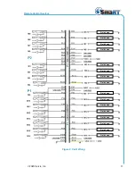
Страница 15: ...em 2020 Cervis Inc 11 Figure 9 Field Wiring Field Load Field Load Field Load Field Load Field Load Field Load Field Load Field Load Field Load Field Load Field Load Field Load Field Load Field Load Fi...

Страница 16: ...GHz RF Power 2 mW License License free Modulation DSSS Antenna Internal Enclosure Dimensions 9 x 3 x 1 231 8 mm x 79 4 mm x 31 8mm Total Weight 15 2 oz 430 9 gr Durability High impact polymer case Pol...

Страница 17: ...cceleration 10 0 g peak shock acceleration INDICATORS 5 In Green Input On Out Green Output On Health Green Pulse sec OK TX RX Green Receive Red Transmit Power Amber OK Red Green Fault ENCLOSURE Dimens...

Страница 18: ...SmaRT 218 918 U053 5 1 SmaRT_OO x18_Sys 14 7 0 BU x16F Output Current Derating Curve Figure 10 Base Unit Output Current Derating Curve...

Страница 19: ...mal condition Out LED pulsing Amber Indicates an over current condition Out LED slowly pulsing Amber Over temperature indication In LED not active Check to make sure that voltage to channel is less th...

Страница 20: ...t www cervisinc com The Cervis Inc and SmaRT Wireless logos are trademarks of Cervis Inc Contact via Phone 724 741 9000 2020 Cervis Inc All rights reserved Content is subject to change without notice...

Отзывы: