background image


7

/

15


3. 

Connect the milling unit and the vacuum unit with the control cable included. 

4. 

Connect the unit to mains (230 V/50 or 60 Hz). 

5. 

Select the correct frequency using the frequency selector (13). 

6. 

Turn on the mains switch (34). 

 The vacuum process will not begin until the milling unit is activated. 

2.4   Electrically connecting the unit  

(see Fig. 3 on page 5 and Fig. 7 on page 10) 

1. 

Connect the unit to mains (230V/50 or 60 Hz) using the mains cable included 
(socket (8)). 

2. 

Turn on the mains switch (34). The indicator (35) will light in green. 


Fig. 3: Panel with control elements 

34 

Mains switch 

36 

Service indicator


35   

Mains switch indicator 


3   Operation 

3.1   Checking the filtration module  

(see Figs. 1 and 2 on page 4) 

Caution   

The CERCON CLEAN single-user vacuum-cleaning unit must not be 
operated without an ultra-fine filter (31) and a filter bag (11), both correctly 
installed and undamaged. 

1. 

Open the two clamp locks (3) and remove the cover (2). 

2. 

Check to ensure that the ultra-fine filter (31) is undamaged and tightly 
pressed against sealing surfaces (24) using the ledge (29). 

3. 

Check to ensure that the two M6 nuts (28) are tightened firmly and 
equally. 

4. 

Check to ensure that the mounting cover (5) is tightly screwed into 
place using the two thumb screws (6). 

5. 

Check to ensure that the filter bag (11) is inserted properly in the 
basket (12) and that it is undamaged. 

6. 

Check to ensure that the plastic connector (10) of the filter bags is 
seated tightly on the connecting duct (15). 

7. 

Replace the cover (2) and close the two clamp locks (3). 

3.2   Air volume control 

Note     

The fuller the filter bag (11), the less powerful the vacuum. 

Содержание Clean 230VAC

Страница 1: ...Instructions for Use Designation of the unit Single user vacuum cleaner unit Unit type CERCON CLEAN 230VAC Unit No _____________________ ...

Страница 2: ...ed for the safety instructions in these Instructions for Use 3 2 Powering Up 3 2 1 Unpacking the single user vacuum cleaner unit 3 2 2 Short description of the unit Identification of components 3 2 3 Turning on the unit 5 2 4 Electrically connecting the unit 5 3 Operation 6 3 1 Checking the filtration module 6 3 2 Air volume control 6 3 3 Automatic turn off and filter change indicator 6 4 Cleaning...

Страница 3: ... cleaning or repair work and physically disconnect from mains by unplugging the mains cable Because the vacuumed dust can constitute a health hazard care must be taken and insure that the filter bag and the ultra fine filter are inserted correctly at all times and that they are undamaged Before accessing the electrical component of the unit the unit must be disconnected from mains 1 3 Authorized o...

Страница 4: ... box weight approximately 25 kg 5 Check to ensure that all components are present Documentation Mains cable Control cable Vacuum hose 40 mm in diameter 2 m in length with two 40 mm connecting ducts Single use filter bags paper 5 ea 2 2 Short description of the unit Identification of components The CERCON CLEAN single user vacuum cleaning unit features a powerful noise reduced high capacity pressur...

Страница 5: ...C dust1 Fig 1 View from front left 1 Casing 2 Cover 3 Clamp locks 2 ea 4 Panel 5 Mounting cover 6 Thumb screws 2 ea 7 Connection socket for control cable 8 Primary power socket 230 V 50 Hz 9 Air outlet 13 Frequency selector 50 60 Hz 1 As defined in Sicherheitstechnisches Informations und Arbeitsblatt der Berufsgenossenschaft 510210 ...

Страница 6: ... M6 nuts 2 ea 17 Cover for filter bag 29 Ledge with longitudinal bores 20 Pre filtration chamber 30 Electrical wiring central 21 Floor rollers 31 Ultra fine filter 22 Screws for bottom space 9 ea 32 Ultra fine filtration chamber 23 Vacuum motor 2 3 Turning on the unit see Figs 1 and 2 on page 4 1 Check the filtration module see Section 3 1 2 Connect the 40 mm diameter hose to the milling unit keep...

Страница 7: ...page 4 Caution The CERCON CLEAN single user vacuum cleaning unit must not be operated without an ultra fine filter 31 and a filter bag 11 both correctly installed and undamaged 1 Open the two clamp locks 3 and remove the cover 2 2 Check to ensure that the ultra fine filter 31 is undamaged and tightly pressed against sealing surfaces 24 using the ledge 29 3 Check to ensure that the two M6 nuts 28 a...

Страница 8: ...rn off function has turned off the unit cycling the unit off and on and tapping the filter bag 11 will allow the operator to keep working for a little while longer without having to replace the filter bags 2 To tap the filter bag 11 open the two clamp locks 3 and remove the cover 2 see Figs 1 and 2 on page 4 Note If the automatic turn off function has turned off the unit filter change indicator is...

Страница 9: ... pressurized air to remove any dust present in the filtration chamber 20 Do not allow any foreign matter to enter the air intake opening 26 because this might damage the vacuum motor 5 Insert the new filter bag snugly and check the filtration module see Section 4 2 4 2 Inserting the filter bag see Fig 1 on page 4 and Figs 6 and 7 on page 9 1 Fold new filter bag 11 as shown in Fig 5 and insert into...

Страница 10: ... ultra fine filter see Figs 1 and 2 on page 4 and Fig 6 on page 9 Note Approximately every tenth time the filter bag 11 is changed the ultra fine filter 31 should be removed and cleaned dry cleaning process or replaced We will be happy to clean the ultra fine filters 31 for you by way of a filter exchange In this way you can be certain that only type tested filters pursuant to DIN EN 60 335 2 69 Z...

Страница 11: ...a fine filter 31 6 Slide the ledge 29 onto the threaded pins from above 7 Tighten the two M6 nuts 28 firmly and equally 8 Tightly screw the mounting cover 5 into place using the two thumb screws 6 9 Check the filtration module see Section 3 1 Fig 6 Changing the ultra fine filter 4 4 Service indicator see Fig 3 on page 5 If the Service indicator is lit the vacuum motor 23 needs replacing The vacuum...

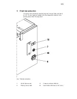
Страница 12: ...two fine wire fuses main fuse 6 3 A T The two fuses are located in the fuse drawer 40 inserted in the primary power socket housing 8 ist Fig 7 Electrical protection 7 Control cable socket 13 Frequency selector 50 60 Hz 8 Primary power socket 40 Fuse drawer with fuses 6 3 A T 2 ea ...

Страница 13: ...y 10 kg depending on the type of dust Electrical protection 2 6 3 A T mains connection Weight ca 25 kg 7 Warranty conditions This unit complies with present day safety requirements and has been tested extensively before leaving the factory We offer you a 24 month warranty and undertake to perform free of charge any repairs that may become necessary due to defects in material or workmanship This wa...

Страница 14: ...depot Rodenbacher Chaussee 4 Postfach 1364 Sender 63403 Hanau Germany Date Signature 8 EU Declaration of Conformity pursuant to EC Machine Directive 98 37 EC We declare that the machine described below conforms to the basic health and safety requirements of the EC Directives in design and construction This declaration shall be void if the machine is subjected to any modifications not authorized by...

Страница 15: ...or measurement control and laboratory use DIN EN 55 014 Funk Entstörung von elektrischen Betriebsmitteln und Anlagen DIN EN 55 104 Elektromagnetische Verträglichkeit Störfestigkeitsanforderungen Kategorie 1 The following national technical standards were applied DIN EN 60335 2 69 ZH 1 487 Einrichtung zum Abscheiden gesundheitsgefährlicher Stäube mit Rückführung der Reinluft in die Arbeitsräume A T...

Отзывы: