Central Machinery 38142 Скачать руководство пользователя страница 15

Page 15

For technical questions, please call 1-800-444-3353.

Item 38142 


REV 12f

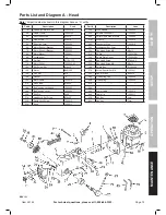
Parts List and Diagram A - Head

Note:

  All part numbers shown in this diagram have an “A” suffix

Part #

Description

Code

1A

Head w/pointer and trim

1302001A

2A

Cable Clamp

1502014A

3A

Pan Head Screw

M5x12

4A

Hex. Screw

M8x16

5A

Adjusting Lever

1502006

6A

Motor Support Bracket

1502002

7A

Motor Support Bracket

1502003

8A

Motor Mount

1502007

9A

Lockwasher

˜12

10A

Nut Hex.

M12 x 1.75

11A

Motor Pulley

1505005-02

12A

Skt. Screw Set

M6x10

13A

Motor

B881262

14A

Hex. Nut

M8

15A

Washer

˜8

16A

Motor Cable

1502016

17A

Hex Screw

M8x20

18A

Belt Tension Lock Knob

1502005

19A

Belt Tension Lever

1502004

20A

Roll Pin

6x26

21A

Head Lock Set Screw

M8x25

22A

Depth Lock Screw

1504012

23A

Knob

1304011

Part #

Description

Code

24A

Feed Handle

1304005

25A

Spindle Feed Shaft

1304002

26A

Collar Depth Stop, w/scale

1304003

27A

Stop Pin

1304010

28A

Connector Wire

1502019

29A

Lockwasher Ext. 5mm

˜5

30A

Pan Head Screw M5

M5x12

31A

Switch

1502010-01

33A

Switch Plate Cover

1502009-01

34A

Pan Head Screw

ST4.2x9.5

35A

Pan Head Screw M5

M5x12

36A

Switch Box

E1302008

37A

Screw-Special Set M8

1302021

38A

Hex. Nut M12

M12x1.5

39A

Quill Spring Cap

1504008

40A

Quill Spring

1504009

41A

42A

43A

Power Cable

1302015

44A

Cable Tie

1502017

45A

Hex Key

4mm

46A

Hex Key

3mm

SAFETY

OPERA

TION

MAINTENANCE

SETUP

Содержание 38142

Страница 1: ......

Страница 2: ...rnings Read all safety warnings and instructions Failure to follow the warnings and instructions may result in electric shock fire and or serious injury Save all warnings and instructions for future reference 1 KEEP GUARDS IN PLACE and in working order 2 REMOVE ADJUSTING KEYS AND WRENCHES Form habit of checking to see that keys and adjusting wrenches are removed from tool before turning it on 3 KE...

Страница 3: ... frees both hands to operate tool 13 DON T OVERREACH Keep proper footing and balance at all times 14 MAINTAIN TOOLS WITH CARE Keep tools sharp and clean for best and safest performance Follow instructions for lubricating and changing accessories 15 DISCONNECT TOOLS before servicing when changing accessories such as blades bits cutters and the like 16 REDUCE THE RISK OF UNINTENTIONAL STARTING Make ...

Страница 4: ...ce damaged or worn cord immediately 125 V 3 Prong Plug and Outlet for up to 125 V and up to 15 A Grounding Pin 7 This tool is intended for use on a circuit that has an outlet that looks like the one illustrated above in 125 V 3 Prong Plug and Outlet The tool has a grounding plug that looks like the plug illustrated above in 125 V 3 Prong Plug and Outlet 8 The outlet must be properly installed and ...

Страница 5: ...mical known to the State of California to cause cancer and birth defects or other reproductive harm Wash hands after handling California Health Safety Code 25249 5 et seq 18 The warnings precautions and instructions discussed in this instruction manual cannot cover all possible conditions and situations that may occur It must be understood by the operator that common sense and caution are factors ...

Страница 6: ...plug the tool from its electrical outlet before performing any procedure in this section Note For additional information regarding the parts listed in the following pages refer to the Assembly Diagram near the end of this manual Mounting Secure the tool to a supporting structure before use Before assembly bolt the Base to a flat level solid workbench capable of supporting the weight of the drill p...

Страница 7: ...he rack easily without binding and will also rotate about the column evenly and without binding 9 IF TOO TIGHT Nudge up the Arm Locking Handle and slacken off the Collar Set Screw Adjust to give a greater working clearance between the rack and collar tighten the set screw and test again 10 Insert the table into its housing on the arm and secure with the Table Clamp 13B Head to Column 1 It may be n...

Страница 8: ...rease and install in its mounting between the motor and spindle pulleys 3 Consult the chart inside the pulley cover or the Drill Speed chart in this manual and install the belts in the positions corresponding to spindle drill speed required 4 Turn the Belt Tension Lever 19A counterclockwise so that tension is applied to the belts see Head Assembly diagram Tension is correct when the belts deflect ...

Страница 9: ...ning the Bevel Table Locking Screw E and tilting to the required angle A scale F is provided on the arm measured in degrees to assist in setting the required angle For all normal operations the table should be set at 0 4 TO ENSURE THAT THE DRILL IS ENTIRELY PERPENDICULAR TO THE TABLE insert a piece of straight round bar in the chuck place a square on the table and bring it up to the round bar Adju...

Страница 10: ...pindle drill speed required 4 When the belts have been correctly positioned tighten them by turning the Belt Tension Lock Knobs 18A until the belt deflects by approximately 1 2 at its center when using reasonable thumb pressure Lock this position in with the two Locking Knobs 18A Note If the belt is too long to be properly tensioned it must be replaced Figure C Drill Speed Table The table above sh...

Страница 11: ... drill 8 FOR FLAT WORK lay the piece on to a wooden base and clamp it down firmly against the table to prevent it from turning 9 FOR SMALL MATERIALS that cannot be clamped to the table use a drill press vise Make sure the vise is clamped or bolted to the table 10 WHEN DRILLING COMPLETELY THROUGH WOOD always position a piece of scrap wood between the material and the table to prevent splintering on...

Страница 12: ...blem corrected before further use Cleaning Maintenance and Lubrication 1 BEFORE EACH USE inspect the general condition of the tool Check for loose hardware misalignment or binding of moving parts cracked or broken parts damaged electrical wiring and any other condition that may affect its safe operation 2 AFTER USE wipe external surfaces of the tool with clean cloth 3 WARNING If the supply cord of...

Страница 13: ...ong or small diameter extension cord 1 Allow machine to work at its own rate 2 Keep cutting accessories sharp Replace as needed 3 Wear ANSI approved safety goggles and NIOSH approved dust mask respirator while blowing dust out of motor using compressed air 4 Eliminate use of extension cord If an extension cord is needed use one with the proper diameter for its length and load See Table A on page 3...

Страница 14: ...taining Ring 17mm 8 Retaining Ring 11mm 9 Ball Bearing 60201 10 Quill Gasket 1303003 11 Quill 13030002B 12 Ball Bearing 60204 13 Spindle Shaft 13003001A Part Description Code 14 Arbor 1503007 15 Chuck 1503009A 16 Chuck Key 1503010A 17 Wedge Drift 1503008 18 Ball Bearing 60202 19 Idler Pulley 1505006 02 20 Idler Pivot 1705007 21 Knot 1505008 22 Pan Head Screw M5x8 23 Pulley Cover 13050000A 24 Washe...

Страница 15: ...2016 17A Hex Screw M8x20 18A Belt Tension Lock Knob 1502005 19A Belt Tension Lever 1502004 20A Roll Pin 6x26 21A Head Lock Set Screw M8x25 22A Depth Lock Screw 1504012 23A Knob 1304011 Part Description Code 24A Feed Handle 1304005 25A Spindle Feed Shaft 1304002 26A Collar Depth Stop w scale 1304003 27A Stop Pin 1304010 28A Connector Wire 1502019 29A Lockwasher Ext 5mm 5 30A Pan Head Screw M5 M5x12...

Страница 16: ...sportation charges prepaid Proof of purchase date and an explanation of the complaint must accompany the merchandise If our inspection verifies the defect we will either repair or replace the product at our election or we may elect to refund the purchase price if we cannot readily and quickly provide you with a replacement We will return repaired products at our expense but if we determine there i...

Отзывы: