MANUAL AND AUTOMATED
RESILIENT SEAT BUTTERFLY VALVES
INSTALLATION
and
MAINTENANCE
INSTRUCTIONS
CENTER
LINE
Страница 1: ...MANUAL AND AUTOMATED RESILIENT SEAT BUTTERFLY VALVES INSTALLATION and MAINTENANCE INSTRUCTIONS CENTER LINE ...
Страница 2: ...lange Preparation 4 Installation Tools 4 Required Bolting 4 Unpacking and Storage Instructions 4 Pre Installation Procedure 5 Valve Installation Procedure 5 6 Flange Bolting Recommendations 7 Maintenance Instructions Safety Precautions 8 General Maintenance 8 Butterfly Valve Disassembly 8 Butterfly Valve Assembly 8 9 Check Valve Disassembly 9 Check Valve Assembly 10 Ratchet Handle Mounting Procedu...
Страница 3: ...ns in seating torque Flange and Pipe Schedule Compatibility The Center Line RSBFV is designed to fit between standard piping flanges as follows ANSI 125 Cast Iron Flanges All Sizes ANSI 150 Steel Flanges Schedule 40 All Sizes ANSI 150 Steel Flanges Schedule 80 2 to 10 ANSI 300 Steel Flanges Schedule 40 Series 225 Lug 2 to 12 only When using Schedule 80 piping special care must be taken to make sur...
Страница 4: ...terference and initial torque build up during valve installation In general it is preferable to install RSBFV s with the shaft in a horizontal orientation In this position shaft and disc weights are evenly distributed minimizing seat wear Additionally any foreign matter which may accumulate at the bottom of the disc and shaft is effectively removed each time the valve is opened Center Line butterf...
Страница 5: ...essary For Check Valves a Note the opening direction of the disc for proper valve orientation b Place the valve between the flanges using the four 4 alignment holes provided c Install the remaining flange bolts shifting the valve as necessary to permit the bolts to pass by the valve body Hand tighten bolts as necessary 2 3 4 5 6 Before completing the tightening of any bolts the valve should be cen...
Страница 6: ...gagement even on both sides of valve Incorrect Disc in closed position Gaskets installed between valve and mating flanges Correct No flange gaskets used Disc in the almost closed position Figure 2 Centering and Flanging of Valve Figure 3 Flange Bolt Tightening Sequence Figure 4 Final Valve Alignment and Tightening of Flange Bolts 1 15 8 12 4 10 6 14 2 16 7 11 3 9 5 13 1 8 4 6 2 7 3 5 1 8 4 6 2 11 ...
Страница 7: ... 10 000 13 000 3 500 100 400 20 Series 200 1 1 8 7 20 11 250 14 500 4 250 100 400 20 Series 225 1 1 8 7 16 11 250 4 250 100 400 4 ea 5 000 3 250 100 400 24 Series 200 1 1 4 7 20 12 750 15 125 4 750 150 500 24 Series 225 1 1 4 7 16 12 750 4 750 150 500 4 ea 5 250 3 750 150 500 30 Series 200 1 1 4 7 24 13 750 4 500 150 500 4 ea 5 750 4 250 150 500 Center Line Wafer And Lug Valves 2 30 ANSI 125 150 B...
Страница 8: ...at body 5 Disc 1 2 3 4 5 6 Position valve flat with the disc in the closed position Loosen the taper pin s from the valve disc using a hammer and punch Note Punch should be of same size or larger diameter as small end of taper pin to avoid mush rooming of taper pin Remove taper pin s from disc Extract the valve shaft from the body using a twisting motion Remove the valve disc from body making sure...
Страница 9: ... When the stem is removed the springs 5 behind the check plates 2 will be released On sizes 8 to 20 thesespringsmust besecurelyheldtopreventrecoil upon loss of tension Remove the check valve plates 2 from the valve insert Note the location of the thrust washers 6 These must be replaced in the same location upon reassembly Butterfly Valve Assembly continued from page 8 6 7 8 9 Insert the shaft thro...
Страница 10: ... the mounting bracket with the appropriate machine bolts and lock washers It may be necessary to rotate the gear shaft slightly to align the mounting holes in the gear with the plate Adjust the stops in the gearbox to position the face of the discparallelwiththefaceofthevalveintheclosedposition and perpendicular to the face of the valve in the open position Check Valve Assembly MAINTENANCE INSTRUC...
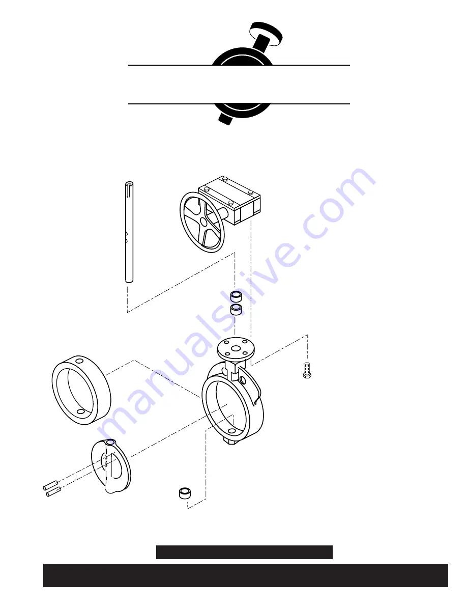
Страница 11: ... Travel Stop 14 larger only 1 Body 2 Disc 3 Seat 4 Shaft 5 Taper Pin 6 Key 7 O Ring 8 Bushing 9 Bushing 10 Bushing 1 Body 2 Disc 3 Shaft 4 Taper Pin 5 Key 6 Packing V Ring 7 Packing Retainer 8 Washer Qty 2 9 Bushing 10 Bushing 11 Snap Ring Parts List MAINTENANCE INSTRUCTIONS Item Description Recommended Spare Parts Item Description Recommended Spare Parts Series 200 205 225 Butterfly Valve Series ...
Страница 12: ... Abrasion Resistant Buna 2 Black Neoprene 3 EPDM 5 Low Temp Viton 6 Hypalon 7 PTFE Buna L High Temp Viton P EPDM Food Grade V No Seat X Viton O White Buna Food Grade W Peroxide Cured Buna 8 Potable Water EPDM D White Buna B Handle DIT 2 Handle Infinite Adjustment 3 Lockable DIT IOL Handle Infinite Adjustment 4 DIT IO Gear Handwheel 5 Gear Chainwheel U Gear W Balance Stop Handwheel G Buried Service...