


3.3 Installation
•
This product is intended to be installed only in restricted access areas as defined by UL60950 and in accordance
with the National Electric Code, ANSI/NFPA 70, or equivalent agencies.
•
The Inverter System may contain output over current protection in the form of circuit breakers. In addition to
these circuit breakers, the user must observe the recommended UL listed upstream and downstream circuit
breaker requirements as defined in this manual.
•
Please use extreme caution when accessing circuits that may be at hazardous voltages or energy levels.
•
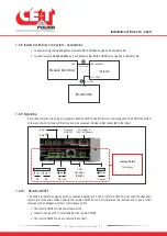
The modular inverter rack is a dual input power supply. The complete system shall be wired in a way that both
input and output leads can be made power free.
•
REG systems and EPC systems that have no AC input wired and connected can be seen as independent power
sources. To comply with local and international safety standards N (output) and PE shall be bonded. The bonded
connection between N (output) and PE must be removed once the AC input is connected.
•
AC and DC circuits shall be terminated with no voltage / power applied.
•
The safety standard IEC/EN62040-1-1 requires that, in the event of an output short circuit, the inverter must
disconnect in 5 seconds maximum. The parameter can be adjusted on Inview; however, if the parameter is set at
a value > 5 seconds, an external protection must be provided so that the short circuit protection operates within
5 seconds. Default setting is 60 seconds.
•
The system is designed for installation within an IP20 or IP21 environment. When installed in a dusty or humid
environment, appropriate measures (air filtering) must be taken.
•
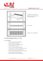
All illustrations in the manual are for general reference, refer to the technical drawing which is received along
with the system for exact information.
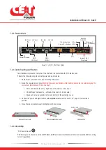
3.3.1 Handling
•
The cabinet shall not be lifted using lifting eyes.
•
Remove weight from the cabinet by unplugging the inverters. Mark inverters clearly with shelf and position for
correct rebuild. This is especially important in dual or three phase configurations.
•
Empty inverter positions should not be left open. Replace either with module or dummy cover.
3.3.2 Surge and transients
The mains (AC) supply of the modular inverter system shall be fitted with Lightning surge suppression and Transient
voltage surge suppression suitable for the application at hand. Manufacturer’s recommendations of installation shall be
adhered to. Selecting a device with an alarm relay for function failure is advised.
Indoor sites are considered to have a working lightning surge suppression device in service.
•
Indoor sites Min Class II.
•
Outdoor sites Min Class I + Class II or combined Class I+II. The modular inverter system/rack can reach
hazardous leakage currents. Earthing must be carried out prior to energizing the system. Earthing shall be made
according to local regulations.
3.3.3 Other
•
Isolation test (Hi-Pot) must not be performed without instructions from the manufacturer.
Warranty and Safety Conditions
8
- Bravo 10 - 48/230 - User manual - v1.2
Содержание Bravo 10 - 48/230
Страница 43: ......


