DGM1D
ESPAÑOL
ES
ENGLISH
EN
INSTALLATION MANUAL
Range:
Integrated Access Control /
MANUAL DE INSTALACIÓN
Gama:
Control de accesos autónomo
Controlador Mifare
®
de 1 puerta
1-Door Mifare
controller/reader system
Group Products
Страница 1: ...AÑOL ES ENGLISH EN INSTALLATION MANUAL Range Integrated Access Control MANUAL DE INSTALACIÓN Gama Control de accesos autónomo Controlador Mifare de 1 puerta 1 Door Mifare controller reader system Group Products ...
Страница 2: ... a las 100 posibles puertas portón de entrada Cabeza DGM1D Muy alta resistencia al fuego Programación muy sencilla Programación de tags en el PC Transferir la información al programador PCV123D Descargar la programación al DGM1D de manera inalámbrica poniendo el PCV123D en la cabeza Mifare Tags ilimitados por instalación modo lista negra o hasta 200 tags modo lista blanca Posibilidad de borrar los...
Страница 3: ...de la central se iluminará con un color rojo fijo en cuanto comience a parpadear significará que se ha terminado de borrar toda la información Corte una vez más la alimentación del DGM1D Retire el jumper JP2 Alimente el DGM1D La central ya está preparada para volver a programarse Nota El Tag Maestro no se elimina Programación del tiempo de activación del relé de cerradura La temporización se reali...
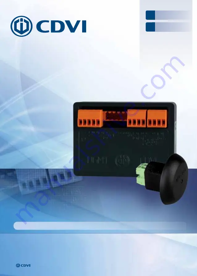
Страница 4: ...dor de salida J1 1 B BUS RS 485 J3 1 NO Contacto normalmente abierto de relé 2 A BUS RS 485 2 C Común de relé 3 TX Conexión a programador PCV123D 3 NC Contacto normalmente cerrado de relé 4 RX Conexión a programador PCV123D 4 12 Alimentación 12 Vac dc 5 GND Conexión a programador PCV123D 5 V Alimentación 12 Vac dc 3 KIT DE MONTAJE Arandela T25 Jumpers Varistor Cabeza de lector DGM1D 1 3 1 1 JP2 QU...
Страница 5: ...L DE INSTALACIÓN De 2 a 10 metros Cable coaxial apantallado Hasta 2 metros Cable de 2 pares apantallado LED Rojo LED Rojo LED Verde LED Verde Este producto incluye un varistor Debe instalarse en paralelo a los terminales del dispositivo de cierre para proteger al DGM1D de los picos de tensión provocados durante la activación del mismo dispositivo de cierre Cableado de la cerradura El dispositivo d...
Страница 6: ...ón de la apertura de puerta se puede programar desde 2 hasta 20 segundos usando el PCV123D Al utilizar la interfaz bus INTBUSDGM1D coloque el jumper JP2 en el DGM1D LED ROJO LED VERDE Recomendaciones IMPORTANTES DGM1D Bornes Correspondencia J2 1 ANT Antena 2 GND Antena 3 Led R Conexión de LED rojo 4 Led V Conexión de LED verde J1 1 B BUS RS 485 2 A BUS RS 485 3 TX Conexión a programador PCV123D 4 ...
Страница 7: ...do N C de alarma B 16 Bus RS 485 todos los B deben conectarse en serie C 5 Común de alarma M 1 T 6 Contacto normalmente abierto N O de alarma 12V 2 7 Alimentación 12 Vac dc o 24 Vdc 1 3 Común de conexión exterior 8 Alimentación 12 Vac dc o 24 Vdc 2 4 Datos para conexión a central exterior P1 9 Botón pulsador interior 3 5 M 10 Común P1 y P2 4 1 Común de LED No utilizar P2 11 Botón pulsador exterior...
Страница 8: ...erta N C cerrada N O abierta L Activación de lector de tarjetas N O habilitado N C deshabilitado M Común entre bornes E M y E L A Bus RS 485 todos los A deben conectarse en serie B Bus RS 485 todos los B deben conectarse en serie BornERO de 3 puntos de conexión placa esclava D741 7 Zumbador 8 Señalización visual de color verde 9 Señalización visual de color rojo INTWDGM1 BornES CorrespondENCIAS 1 ...
Страница 9: ...DGM1D debe ser el mismo 26 o 44 bits Al usar el DGM1D con su interfaz INTWDGM1D asegúrese de colocar el jumper JP2 en el DGM1D REcomendaciones importantes Si no desea monitorizar el estado de la puerta haga un puente entre E y M Cable de apantallado Cable SYT1 apantallado Cerradura Ventosa Varistor Hacia otros controladores de puerta INTBUSW Sin jumper Clock deshabilitado Con jumper Clock habilita...
Страница 10: ...NC Contacto normalmente abierto de relé C Común de relé NO Contacto normalmente abierto de relé J1 GND Conexión a programador PCV123D RX Conexión a programador PCV123D TX Conexión a programador PCV123D A Bus RS 485 B Bus RS 485 J5 BP Botón pulsador de salida GND Común de botón pulsador de salida GND Común de conexión exterior DATAS Datos para conexión a central exterior J2 Led V Conexión de LED ve...
Страница 11: ...seña 3 El PCV123D indicará Incorrect site incorrect or password y mostrará un código de error 4 Póngase en contacto con su distribuidor e indíquele el código y la fecha en la que se generó el mismo 5 Su distribuidor se pondrá en contacto con el servicio técnico de CDVI y le harán llegar su contraseña y código de sitio a la mayor brevedad posible Cómo actualizar su central DGM1D Acuda al manual del...
Страница 12: ... access on the 100 doors possible gate Reader Very highly flame resistant Programming Capability Programming of the badges on PC Transfer to the PCV123D Downloading site with a simple contact of the PCV123D on the reader Number of residents on site unlimited black list or limited to 200 badges using white list Cost effective solution Possibility to delete badges for reprogramming Wireless cancella...
Страница 13: ...factory default values Turn off the power on the controller Put JP2 jumper Turn on the power The LED of the reader turns on solid red the reset is completed when the LED starts flashing in red Turn off again the power on the controller Remove jumper JP2 Turn on the power supply the controller is ready to be reprogrammed Note the Master Badge is not deleted Lock time The programming is done with th...
Страница 14: ...tenna 2 GND Exit Pushbutton 3 Led R Red LED 3 GND Ground 4 Led V Green LED 4 BP Push button input J1 1 B BUS RS 485 J3 1 NO Normally open relay output 2 A BUS RS 485 2 C Common relay output 3 TX PCV123D Link 3 NC Normally close relay output 4 RX PCV123D Link 4 12 12V AC DC 5 GND PCV123D Link 5 V 12V AC DC 3 MOUNTING KIT T25 Lock nut Jumpers Varistor Reader DGM1D 1 3 1 1 JP2 Without With White list...
Страница 15: ...for the shield Shielding 5 WIRING DIAGRAM READER Wiring of the TDG1 D from 2 to 10 meters Wiring with a shielded coaxial cable Wiring of the TDG1 D up to 2 meters AWG35 2 pair shielded cable This product comes with a varistor This one has to be mounted directly on the terminals of the lock strike EM lock To secure the system from back electromagnetic fields do not forget to mount the varistor in p...
Страница 16: ... controller unit is 50 meters DGM1D time lock is programmable from 2 to 20 seconds with the PCV123D handheld terminal If using the DGM1D with the reader interface INTBUSDGM1 make sure JP2 jumper is ON RED GREEN IMPORTANT Recommendations DGM1D Terminals Description J2 1 ANT Antenna 2 GND Antenna 3 Led R Red LED 4 Led V Green LED J1 1 B BUS RS 485 2 A BUS RS 485 3 TX PCV123D Link 4 RX PCV123D Link 5...
Страница 17: ...act power supply M 14 common ground E and M or E and L T 3 NO contact Normally open Door strike A 15 RS485 bus All A must be connected together like a chain R 4 NC contact Normally closed Alarm B 16 RS485 bus All B must be connected together like a chain C 5 Common contact M 1 T 6 NO contact Normally open Alarm 12V 2 7 Input voltage 12 V DC or AC or 24 V DC 1 3 Link to external centrol unit 8 Inpu...
Страница 18: ...on ground P1 and P2 P2 Request to enter input E Door position contact N C Door closed et N O Door open L Badge reading authorization contact N O enabled and N C disabled M Common E and M or E and L A RS485 Bus All A must be connected as a chain B RS485 Bus All B must be connected as a chain 3 point TERMINAL block PIGGYBACK BOARD D741 7 Buzzer 8 Visual feedback Green color 9 Visual feedback Red col...
Страница 19: ...d format must be the same Between door controller INTBUSW and bus interface INTW DGM1D Wiegand 26 or 44 bits IMPORTANT RecommEndations EM Input Door status Wire shielded SYT1wire shielded Strike Magnetic lock Varistor To th next reader controller Without jumper without clock With jumper with clock Without jumper 26 Bits With jumper 44 bits Standalone or integrated mode Refer to INTBUSW manual 12 V...
Страница 20: ...RMINALS description J3 12 Power supply 12V AC DC V Power supply 12V AC DC NC Normally closed relay contact C Relay Common NO Normally opened relay contact J1 GND PCV123D link RX PCV123D link TX PCV123D link A RS485 BUS B RS485 BUS J5 BP Request to exit input Push button GND Request to exit input Push button GND Ground DATAS Data to external control unit J2 Led V Green led Led R Red Led GND Antenna...
Страница 21: ...ct Refer to complete limited lifetime warranty on cdvigroup website DGM1D site code and or password 1 Connect the DGM1D to a PCV123D with a serial cable 2 Enter site code 0 0 0 0 0 0 and password 0 0 0 0 in the PCV123D 3 PCV123D puts Incorrect site code or Incorrect password followed by a decryption string 4 Give your decryption string to CDVI support team indicating the controller date 01 01 1998...
Страница 22: ...DGM1D 1 Door Mifare controller reader system INSTALLATION MANUAL EN 22 cdviberica com cdvigroup com 8 NOTES ...
Страница 23: ...DGM1D 1 Door Mifare controller reader system INSTALLATION MANUAL EN 23 cdviberica com cdvigroup com ...
Страница 24: ... 39 0321 908018 CDVI MAROC Phone 212 0 5 22 48 09 40 Fax 212 0 5 22 48 34 69 CDVI SWEDEN SWEDEN DENMARK NORWAY FINLAND Phone 46 0 31 760 19 30 Fax 46 0 31 748 09 30 CDVI UK UNITED KINGDOM IRELAND Phone 44 0 1628 531300 Fax 44 0 1628 531003 CDVI Group FRANCE Headquarter Siège social Phone 33 0 1 48 91 01 02 Fax 33 0 1 48 91 21 21 All the information contained within this document photos drawing fea...