Installation and Troubleshooting Guide
NOTE: This installation is to be completed by an Authorized Dealer or Professional Service
Technician. For questions regarding installation or warranty, call CDI Tech Support
at 866-423-4832. Do not return to the Dealer or Distributor where the part was purchased.
Contact CDI Electronics Directly for Return Materiel Authorization.
CDI Electronics, LLC
353 James Record Road SW
Huntsville, AL 35824 USA
Web Support: www.
cdielectronics.com
Tech Support: 1-866-423-4832
Order Parts: 1-800-467-3371
All rights reserved. Reproduction or use of content, in any manner, without express written permission by CDI Electronics, LLC., is prohibited.
Rev D
10/4/2018 Page - 1 of 2 QF-358
CDI P/N: 197-0001 Yamaha Voltage Regulator
Replaces P/N: 6R3-81960-00-00 and 6R3-81960-10-00
WARNINGS:
This product is designed for installation by a professional marine mechanic. CDI cannot be held liable for
injury or damage resulting from improper installation, abuse, neglect or misuse of this product.
DO NOT USE A MAINTAINENCE FREE, AGM OR DRY CELL BATTERY WITH THIS TYPE
REGULATOR/RECTIFIER!!!
NEVER DISCONNECT THE BATTERY WHILE THE ENGINE IS RUNNING AS THIS MAY BURN OUT THE
REGULATOR/RECTIFIER. If the boat is equipped with a battery switch, make sure that it is a make before
break type.
INSTALLATION
1. Disconnect the negative battery cable.
2. Disconnect and remove the old regulator/rectifier.
3. Install the new regulator/rectifier, using the original mounting bolts.
4. Connect the Black wire to a clean engine ground.
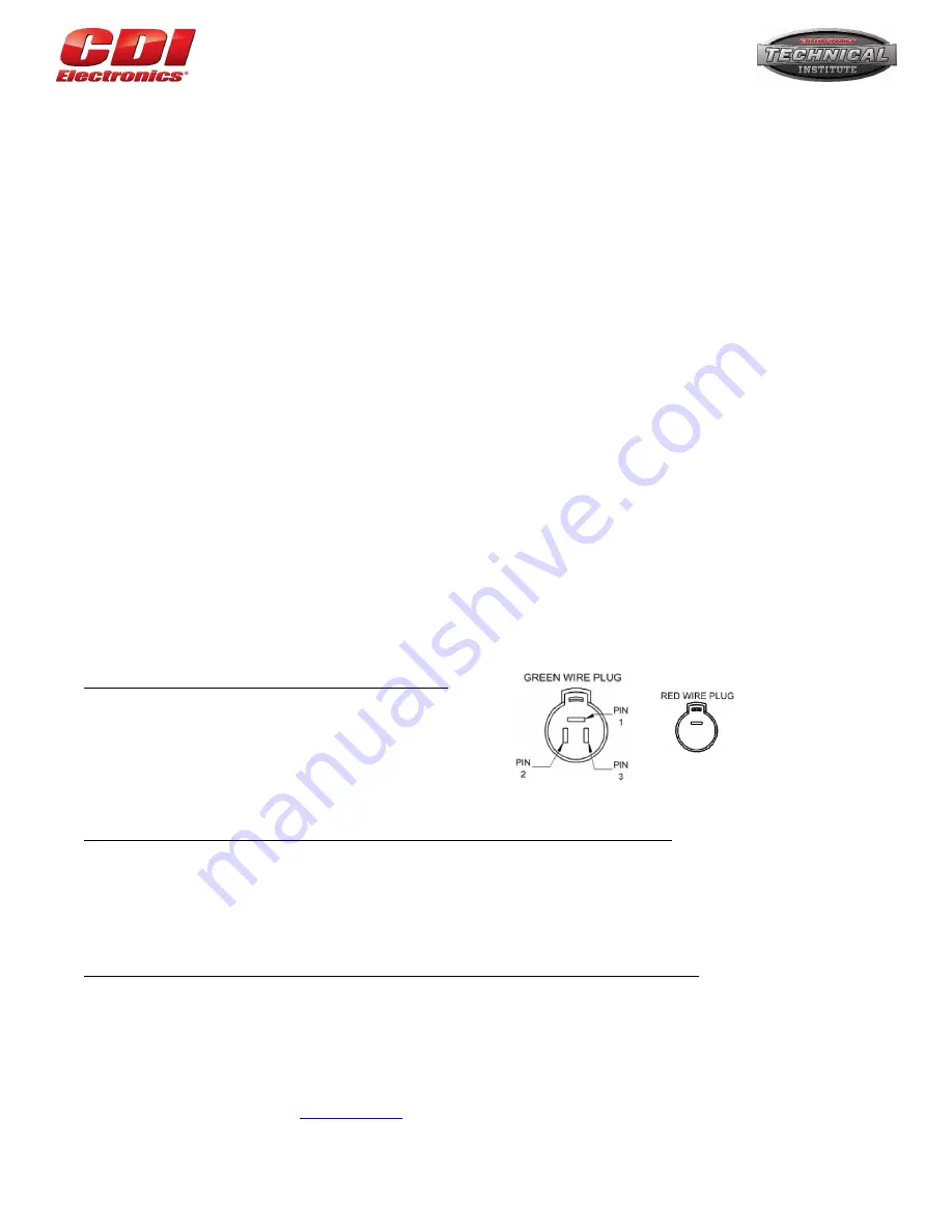
5. Connect the stator’s 3 wire connector to the new regulator/rectifier.
6. Connect the Red wire with the Round connector from the harness to the mating connector from the regulator/rectifier.
7. Connect the Red wire with the bullet connector to the mating connector going to the fuse if present. If there is no connection for this
wire, use a cable tie to tie it out of the way so it does not short out.
8. Reconnect the negative battery cable.
TROUBLESHOOTING
BATTERY IS NOT BEING CHARGED:
1. Clean all Battery cables, engine and battery connections, both on the engine and on the battery.
2. Install a clamp on ammeter capable of reading at least 30 amperes on the Red battery cable connected to the starter solenoid.
Start the engine and see if the ammeter is showing a charge going into the battery. If so, swap out the battery for a known good
one. If the engine now shows a charge going into the battery, the old battery is defective.
3. Check the resistance between the stator’s Green wires as follows:
Read From
Read To
Disconnected
Green 1
Green 2
0.27 to 0.43 Ω
Green 1
Green 3
0.27 to 0.43 Ω
Green 2
Green 3
0.27 to 0.43 Ω
4. Disconnect all connections to the Regulator/Rectifier. Then, using a Multimeter set to diode scale, check the Diodes between the
Regulator/Rectifier’s Green wires and the Red Wire as follows:
Red Meter Lead Connection
Black Meter Lead Connection
Reading
Green 1
Red Lead from Regulator/Rectifier 0.4 to 0.6
Green 2
Red Lead from Regulator/Rectifier 0.4 to 0.6
Green 3
Red Lead from Regulator/Rectifier 0.4 to 0.6
Red Lead from Regulator/Rectifier
Green 1
Open or No Reading
Red Lead from Regulator/Rectifier
Green 2
Open or No Reading
Red Lead from Regulator/Rectifier
Green 3
Open or No Reading
5. Check the DVA voltage on stator’s Green wires as follows:
Read From Read To
Disconnected
Connected
At 1500 RPM
At 3500 RPM
Green 1
Green 2
7V (at cranking) 7V (at cranking)* 13 V*
11 V*
Green 1
Green 3
7V (at cranking) 7V (at cranking)* 13 V*
11 V*
Green 2
Green 3
7V (at cranking) 7V (at cranking)* 13 V*
11 V*
*Connected to the Regulator/Rectifier. If the voltage is too high, the Regulator/Rectifier may be defective. If the voltage is too low,
the stator is likely defective.


