22
REVO PC
User’s manual
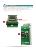
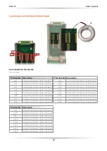
5.1 Command terminals
Warning:
Before connecting or disconnecting the unit check that power and control cables are
isolated from voltage sources.
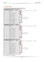
Terminal Block MC1
Terminal MC1
Description
1
+24Vdc
AUX Voltage
2
GND 0Vdc
3
- Common Digital Input
4
+ Digital Input 1 (Enable)
5
+ Digital Input 2
6
+ Digital Input 3
7
+ Digital Input 4
8
RS485 A+
Modbus RTU Slave 1
9
RS485 B-
10
RS485 A+
Modbus RTU Slave 2
11
RS485 B-
12
Not connected
13
GND (0V)
14
C - Common contact alarm relay output
15
NC - Normally Close contact alarm relay output
16
NO - Normally Open contact alarm relay output
Terminal Block MC2
Terminal MC2 Description
1
+24Vdc
OUT
2
GND 0V
3
+12Vdc
OUT 12V 30mA max
4
RS485 A+
Modbus RTU Slave 3
5
RS 485 B-
Terminal Block M1
Terminal M1 Description
1
L1 (R)
2
Not connected
3
L2 (S)
4
Not connected
5
L3 (T)
6
Not connected
7
N
8
Not connected
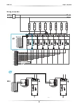
dc
dc
M1-7
1
6
3
4
ISO1
DI-4
TLP181
M1-6
1
6
3
4
ISO2
DI-3
TLP181
M1-5
+
-
1
6
3
4
ISO3
DI-2
TLP181
M1-4
M1-3
M1-2
M1-1
1
6
3
4
ISO4
ENABLE
DI-1
TLP181
+5V
Digital Input
Содержание REVO PC M-RPC
Страница 2: ......


