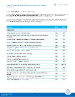

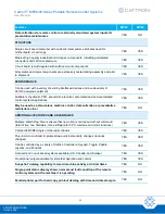


Cattron™ MP96/48 Series Portable Remote Control Systems
User Manual
46
68C-MP96/48-RD-EN
Version 006
5.4
Preset Frequency Selections
– Model R1HN Receiver Only
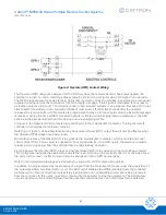
In order for the receiver and the controller to communicate, they must be set to the same operating frequency and
address. Cattron MP Series receivers offer several factory preconfigured frequency selections for maximum
versatility. While the original factory setting should be adequate for most users, there may be conditions where it
is necessary to change the operating frequency. Such conditions include installing a spare receiver circuit board
or controller, or when other systems are emitting RF signals that interfere with safe operation. Before making any
change to an MP Series frequency setting, remember that both the controller and the target receiver must be set
to exactly the same operating frequency and address in order to communicate.
Note:
MP Series R1HN receivers allow the customer to select any one of 16 factory preset frequencies. Refer
to the radio frequency programming sheets supplied with the system for a list of the frequencies
available on your receiver.
R2HN receivers and R3HNX transceivers also allow for field programming of 14 additional frequencies
to any frequency desired between 447 MHz and 472 MHz. IF ONE OF THESE RECEIVERS IS
INSTALLED IN YOUR SYSTEM,
SKIP THE PROCEDURE OUTLINED IN THIS SECTION OF THE
INSTRUCTIONS.
Frequencies for licensed systems must NOT be changed. If the frequency for a licensed system needs
to be changed for any reason, including RF interference, contact Cattron at
To change the frequency setting for the system controller, refer to the documentation provided with the controller.
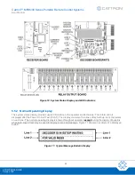
Follow the procedure below to change the Model R1HN receiver board frequency setting to one of the
factory preset frequencies
:
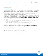
1. Open the cover of the receiver/decoder and remove power from the receiver/decoder by turning off the
circuit breaker on the bottom o
f the electronics chassis, or ‘Gold Box’.
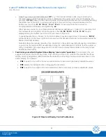
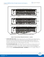
2. Remove the lid from the Gold Box and locate the rotary frequency selector switch on the receiver circuit
board. The switch is shown in Figure 9.
Figure 9: Rotary Frequency Selector Switch Location


