


PHOENIX-60
PHOENIX-60
PHOENIX-60
PHOENIX-60
™
By
Castle Creations
60 amp Brushless Sensorless Speed Control
PHOENIX-60™ User
Guide
Page 1 of 6
Rev 5-date 11/11/03
This document, Phoenix-60™ software, and Phoenix-60™ PCB layout are all Copyright
2002-2003 by Patrick del Castillo and
Castle Creations
Warning!
High power motor systems can be very dangerous! High currents can heat wires and
batteries, causing fires and burning skin. Follow the wiring directions carefully! Model aircraft
equipped with high power motors can kill. Always fly at a sanctioned field. Never fly over or near
spectators. Even though this controller is equipped with a safety arming program, you should still use
caution when connecting the main battery.
1.0
Features of the
Phoenix-60™
:
•
Extremely Low Resistance (.0013 ohms)
•
High rate
adjustable
switching (PWM)
•
Up to 60 amps continuous current with proper air flow, 80
amps surge
•
Five to ten cells with four micro servos
•
Up to twelve cells with three micro servos
•
Twenty cells MAX (with BEC disabled)
•
Dynamic braking ensures folding props fold promptly
•
BEC (3A) provides power to receiver and servos -
eliminates separate receiver battery
•
User Programmable Features:
•
Low-voltage cutoff
•
Over-current Protection
•
Brake Type
•
Throttle Range – fixed/self-adjusting/governor
•
Timing Advance
•
Cutoff Type
•
Soft Start ramp up
•
Switching Frequency
•
Runs motor in forward OR reverse
•
Auto Motor Cutoff with Reset
•
Safe “power on” arming program ensures motor will not
accidentally turn on
•
Low torque “soft start” prevents damage to fragile
gearboxes
•
Auto shut down when signal is lost or radio interference
becomes severe
2.0
Wiring Your
Phoenix-60™
:
Tools required:
Wire cutters
Wire strippers (optional)
Soldering Iron (25-40)
Parts required
:
Solder (rosin core “electronic” solder)
Battery connector
2.1
Servo Ratings with BEC Enabled
Servo Type
5-6 cells
7-8 cells
9-10 cells
11-12 cells
Standard (micro) servos
5
5
4
3
High Torque servos
4
4
3
2
2.2
Adding the Battery Connector
The battery connector is attached to the side of the controller that has only two power wires, and also has the
radio connector. Cut the wires to the length you require on the battery side. Strip off of the wire insulation to
expose just enough wire to attach the battery connector. (Note: if you do not have a pair of wire strippers,
you can use a modeling knife to carefully cut through the insulation around the wire. Then the insulation
should easily pull off the wire.) Attach the battery connector to the wires ENSURING THAT THE
POLARITY (red wire to battery red wire, black wire to battery black wire) IS CORRECT, following the
instructions for the battery connector.
IMPORTANT NOTE:
YOU
MUST
BE SURE THAT THE POLARITY IS CORRECT WHEN
CONNECTING THE SPEED CONTROLLER. Incorrect polarity could permanently damage the controller.
2.3
Connecting the Motor
The motor is connected to the side of the controller that has THREE power wires. Cut the wires to the length
you require on the motor side. DO NOT CUT the wires leading from the motor. Strip the wire insulation to
expose just enough wire to solder the wires to the motor terminals. There should be three wires extending
from the motor. Connect the three speed control wires to the three motor wires. Align the wires carefully
and solder to the motor wires. Ensure that all connections (battery and motor) are correctly polarized.
2.4
Reversing Rotation
Bench test the motor connections noting the rotation of the motor. To change the rotation of the motor, swap
ANY
two motor wire connections.
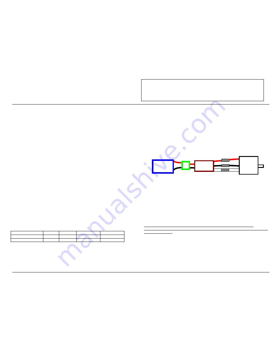
Battery Connector Phoenix-60™ Motor
Fig 1: Motor wiring diagram
2.5
Connecting the Receiver
Connect the receiver lead (the three color twisted wires with a connector on the end) to the throttle channel
on your receiver (usually channel 3). Do not connect a battery to the receiver, as the Phoenix-60™ will
supply power to the receiver and servos through the receiver connector. If you are using more than ten cells,
you must use a separate receiver battery
.
See the section 4.0 (under the heading BEC) for instructions on
disabling the BEC to use a separate receiver battery.
Older AirTronics systems require a minor change to the wiring in the receiver connector supplied with the
speed controller. Reverse the red (power) and brown (ground) wires in the connector plug so that the plug is
orange/brown/red. Use a knife blade to lift the retention tabs on the connector plug to remove the red and
brown wires. Insert the wires back into the plug and press down the retention tab.
3.0
Flying with Your
Phoenix-60™
:
ALWAYS PERFORM A RANGE CHECK BEFORE FLYING WITH ANY NEW SPEED
CONTROLLER! PERFORM YOUR RANGE CHECK AT FULL THROTTLE, HALF THROTTLE
AND NO THROTTLE.
Initialization sequence:
1. Connect the speed controller receiver connector to the proper channel on your receiver (usually channel 3)
2. Turn on your transmitter.
3. Connect the main power battery to the speed controller.
4. The speed controller will remain disarmed (will not operate) until it sees more than four seconds of
“brake” throttle. Move the throttle arm to the lowest position on your transmitter, wait at least four
seconds, and then test the controller to make sure that the throttle operates.
5. Go fly!
6. If the BEC cutoff occurs before you land, you may restart the motor and use low throttle if necessary by
moving the throttle stick all the way down (to the brake position) and then throttling back up. BEC cutoff
will occur again if the voltage drops too low.
Phoenix-60™


