USER & PARTS MANUAL
CS940
16
4
INSTALLATION OF THE MACHINE
4.A
PUTTING THE MACHINE IN PLACE
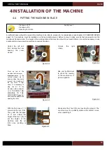
Flat span of 17
bubble level
Flat span of 13
Allen key N.4 & N.5
Figure 4-5
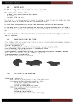
A sufficient space should be around the machine to be able to proceed to its maintenance (see chapter I.2.F NEEDED SPACE
page 13). The machine must be installed on a flat and stable ground. Before to plug it, make sure its feet are adjusted so the
machine is flat and stable. The height of the working table of the machine should be around 900mm, it could be necessary to use
duckboards to ensure small operators a convenient position .
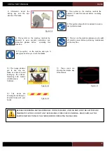
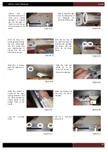
Use your bubble lever
to check the leveling
of the machine as in
picture opposite.
Figure 4-4
Figure 4-1
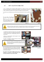
Unlock the left and
front clamps that are
keeping
the
cover
closed.
Unlock
the
right
clamp.
Pivot on top of the
machine the front cover.
Important note : if the
vertical clamps are in
down position, they could
prevent the opening of
the top cover. In that
case, it is necessary to
plug the air to the
machine (refer to chapter
page 22)
and press the pedal while
opening the cover.
Figure 4-3
Figure 4-2
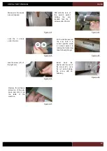
Make sure the 4 feet (14) are touching the ground. The
machine must be perfectly stable and shouldn’t move
when operating it.
With the flat span of 13
mm unlock the nut (CE).
Then, with the flat span
of 17 mm adjust the
height of the foot (14) to
set the height of the
machine. Lock the nut
(CE) once levelling is
done.
CE
14
Содержание CS 940
Страница 1: ...USER PARTS MANUAL Version 5 05 2017 Z27456 Version 1 07 2014 ...
Страница 12: ...USER PARTS MANUAL CS940 12 2 E CUTTING CAPACITY ...
Страница 13: ...USER PARTS MANUAL CS940 13 2 F NEEDED SPACE ...
Страница 37: ...USER PARTS MANUAL CS940 37 ...
Страница 46: ...USER PARTS MANUAL CS940 46 2 E CAPACITE DE COUPE ...
Страница 47: ...USER PARTS MANUAL CS940 47 2 F PLAN D ENCOMBREMENT ...
Страница 71: ...USER PARTS MANUAL CS940 103 V CERTIFICATE CERTIFICAT DE CONFORMITE ...
Страница 72: ...USER PARTS MANUAL CS940 104 ...

