E-34
Using the Optional Optical Communication Unit
Setting up the Optical Communication Unit and
connect the Data Collector
Use only the specified AC Adaptor for Optical Communication Unit to connect to an electrical
outlet. Be sure to connect the AC adaptor and turn on Optical Communication Unit power
before performing any data communication operation with the Data Collector. Power is
supplied to the Data Collector by the Optical Communication Unit.
1
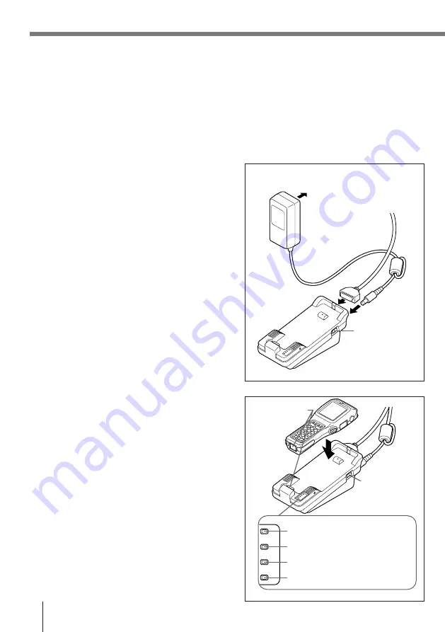
Plug the AC adaptor into an electrical outlet.
2
After making sure that the power switch of the
Optical Communication Unit is in the OFF
position, plug the other end of the AC adaptor
into the AC terminal at the top of the Optical
Communication Unit.
3
After making sure that the power of the Optical
Communication Unit and personal computer is
off, remove the cover and connect one end of
the optional RS-232C cable (DT-881RSC, DT-
882RSC, DT-883RSC, DT-887AX) to the RS-
232C connector at the top of the Optical
Communication Unit. Connect the other end of
the cable to the computer’s RS-232C
connector. When the RS-232C connector is
not used, attach the cover.
4
Turn on the Optical Communication Unit
power, which causes the power indicator to
light up red.
5
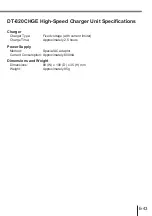
Attach the Data Collector to the Optical
Communication Unit, making sure their
infrared ports come into close contact with
each other. The color of the Optical
Communication Unit power indicator changes
to green when proper connection is achieved.
• The system operation indicator light up
green when system operation is normal and
the Optical Communication is performing or
standing by for data communication with
another Data Collector connected to an
Optical Communication Unit.
• The data communication indicator flashes
green when a data communication
operation starts.
To electrical outlet
Power switch
(OFF)
System operation indicator
Data communication indicator
Charge indicator
Power supply indicator
Power
switch (ON)
Infrared port


