background image

Содержание Cosmo CZ-1

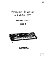
Страница 1: ...irvice Manual I FARTS LIST ELECTRONIC KEYBOARD CZ 1 ...

Страница 2: ...ze tha unit by tha following procedures 1 Turn the power switch off and press INITIALIZE button 2 Turn the power switch on then the display indicates SYSTEM ALL INITIflLIZE Y N 3 Whila pushing INITIALIZE button prat YES button on tha data antry taction of tha panal All tha Mamory Bank data ara initialized than tha display show SYSTEM INITIALIZED ...

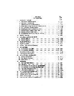
Страница 3: ...ions of Sub CPU 8 MAIN RAM ROM ACCESSES 9 SUB RAMs Si ROM ACCESSES 10 CPU INTERFACE LSI MB64H173 10 1 Function of Each Block 24 3 C13 10 2 Data Transfar Procedures 25 3 C14 10 3 Switch Matrix 29 3 D4 11 KEYBOARD 11 1 Kay Touch Spaed Detection 30 3 D5 1 1 2 Key Matrix 31 3 D6 11 3 Pin Functions of Key Touch Control LSI MSM6200 32 3 D7 1 1 4 Pin Functions of Key ln wface LSI jiPD8049HC 32 3 D7 11 5 ...

Страница 4: ...dt Device 54 3 F2 21 6 Compressor and Expander Circuits 55 3 r J 22 OUTPUT VOLUME CONTROL CIRCUIT 56 3 F4 23 RESET CIRCUIT 57 3 F5 24 MIDI INTERFACE CIRCUIT 58 3 F6 25 ADJUSTMENT 25 1 DAC Offset Voltage Adjustment 59 3 F7 25 2 VSS1 Voltage Adjustment Power Source for MSM6200 59 3 F7 25 3 LCD Brightness Adjustment 59 3 F7 254 After Touch Adjustment 59 3 F7 25 5 VCA Offset Voltage Adjustment 60 3 F8...

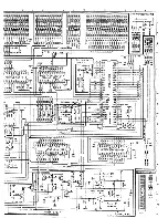
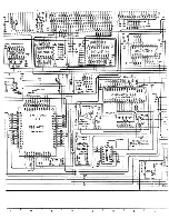
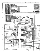
Страница 5: ...CZ 1 1 SCHEMATIC DIAGRAM 11 Main PCB A M5154 MA1M IF flWMCION HIM ...

Страница 6: ...M5154 MA1M IF CC otttif 9wt Sop r Uf Antlof Clrctfil MtSVi Ur 4 l 9 Circuit 1 lSvi VOO oi iIm o r 3w pi r Ur OlfiUI Circuit l SVI Ur M r r Backup t j i VDAC Pt tl P r 3v pi r Ur 0 4 C ftv ri r t 5V 0 4 CM fiir Crown4 Olfttal r Cr 4 OAG ...

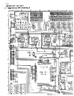
Страница 7: ... 40 D33 47 054 L 035 45 OSt 44 k 037 43 I AO 41 O 39 c 43 a 3a voo H CPU mfirfqct LSI MB64H173 BOTTOM viehi I 1 1 i i i w voo A3I II po 12 0l_ 13 02 U 03 3 04 to 07 TC74MCU04 I osc 777 KM voo vooo NJN455a0O 2 U 21 VOO voo Q Ct 7 7 777 7 777 0 G OfC UFJ8049HC 672 K y nftrfoc LSI dddslsld 7 o nTi f N w f l rt 3 744 5243 n 1 i Siml i NUi 1 1 V00 414 I H 2 AtS 3 TO 2fl 2V0 2 2ti 2y JL VOO 777 0V 050 1...

Страница 8: ...N rpmmifS 3i o Q Ol iJS ua ...

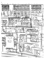
Страница 9: ...Ur 4a U Circuit I ISVI VOO t ll S M r Ur OifiUl Circuit 5VI vM P ui tr Ur MM rf fcw VOAC t llw Smm v Ur 0 A C w rur 1 SVt OAG 0 4 C v rur GravM 0 0 Oifittl r Cr 4 4 OSO Olfiul Sl l OouAtf ADO A 0 Cintirur Gr uM 0 Fr M Gr yM OSI 0S2 0S3 OSS OSO OST _43 42 1 AO 17 I At tO 777 r A2 39 0 0 r A3 1 36 AO 3S A4 3T AS U U V C 5 3 3 8 3552 CPU inttffoct LSI MB64H173 itOTTOM V VI 3 0 0777 AS2 AS4 ASS It 00 ...

Страница 10: ......

Страница 11: ...J ST 7f Urn Q ty UP0U64C 15L 5ir s Isids Ill 1Z 3BJ I T7T 5 1 c x 07 lip MI VD4C 40C 06 05 S3_ 92 00 4t I2 410 4 1 ST 3 3 25 2sT PC4 0 CS CI 4 CC J c C6 C00 V4 EP r i J fd COl 4N7 04C 3 X 21 24 3 a HCC l i j Mceta 4W5 4K4 4 0 4N 39 it 32 7 7 am 1 i T 400 77 o i 3 5 8 5 X I T UP027C256C 20AI54 f J i33fiaStt B5 3 3g i J_ Mf f f 15 5 5 1 X 5 o b n r osc Q 2 Pestf r l 5i rU Po tr OFF Je ec o 00 g 2 I2...

Страница 12: ...12 Sai nPCB IB M5154 MA1M j j i l J J ...

Страница 13: ......

Страница 14: ...1 2 ifiamPC ...

Страница 15: ... VOO J Potlttvo otor Supply lor Olfliol Circuit t 1 VBH Po n o o or Suii v for N aor r Bocruo O SVi V04C I Poo 1 1 Pooor Supply for 0 4 Contorlor l SV OAG 0 A Cofttorior GfOwftd 40C A 0 ContoMor GroaM 0 C Off ial Potor Gro r 0 OSC Olfilot SifAai Ground C C Analog Contor Ground f C Prano Grown r i 5H32 VT30O a TC74MC32P 1 11 41 P Supply I 1 V6II 0P0 I 1 QD 2U 1 AS4 453 j t i 4si 450 f os7 os 3 Sfcf...

Страница 16: ...7 7 7 7 7 7 fn rh O VCC CC OAS 90 DSC AOG 1 ...

Страница 17: ... Tt m fn tn 0A6 0 0 OJC AOG sus Clock puis gmirgror for Music LSI ...

Страница 18: ... IL332N 1 1 4 1X6 0 0 3 A Cjn rit o nj AOC 4 0 Con rt r Qro 4 CPQ Oifl tal t r Cfo wn 03C Oifital Signal Growfttf C C 4naU Ciour Grow a f C Fro Crown VOOQ m I r vn TC74HC32f r i VB 0P0 I 2 5744 I 1X2 I 8 96WI TC7UCU04F o V6 X3 Clock puist gmtraror for Music LSI 777 cioy CONT STC 8 CD C2D CD CS 2 C5D 33 O VOO ...

Страница 19: ...cuit PCB M5154 MA2M jTtlSltC 1 11 71 MOllj CC r IMt oatr Ci toll i l vi r taalof t If c H i ISvi 00 Potiilt o f S M t lot Oi iol Circuit l V o c r tiiu let 0 A t o fi f nlvi til tt oli Po f Vapp 1 to toalog Cin n 1 f o Gro d 3 ...

Страница 20: ...w 0 VC03 C22lft 0 Ir IS OK VC3 Q 6 BO i 10K CtC2 Hl HI BC3 MN32 05 Q M K 777 777 8C3 BC3 TO 5 777 BC3 m o 5 777 BC3 102 IH 8 6 BC2 32 05 C J 5 I 5 MN32 0 O M k 777 777 6C2 8C2 BC2 777 BC2 TV 1 Q 88D3 CIC2IMI BCt 3 2 t8 MN3209I t 38 777 777 BOi BCI BCI 777 BCI 390K NJH4 SS90O I VCCO i l 2iU VCC Q C1C3 HI HI VC4 I CISUC I M 21 13 _ 16V3 Ji CiDOndcr Circuit 2 n CX T ir 8C4 TH Trf Vrtflt aV 777 Oil G ...

Страница 21: ...MA2M TC40 9US 3 1 1 6 1 16 C3 wBG3i ...

Страница 22: ...if uif 3 ISO 3i0P BC4 CISI VCC for 4r log Cu c M 1 1 i 1SV l VCC Ntgoiifff f r Supply fer log Circuit i 15V I VOO Po tti ot r Supply fer O g ui C rcit SVi VD4C Swpp y tor 0 4 C rn n f i 5VI vEE NtactWt p o r Sappiy tor 4 cleo Ctrcwll 7VI CC 4noUf Ground Frost Crow 4 VCC VCC 9 r 0 VC4 W 0VC3 0VC2 OVCI P3M r sovret for Sf erf o hcui c ru i 777 eci ec2 c bc3 bg H TH 9 9 VCC x ch hi 777 CC SOS mi a i ...

Страница 23: ...10 777 777 777 BC4 BC4 CC ...

Страница 24: ......

Страница 25: ......

Страница 26: ...tl MCIIOM W T fftff ft TO Ml B1SL AOL m Ml ttr circ H l t l VCC N t ilti M y Im tatUf Clrc ll l l Vfikl tit teffly Ur UO IRUAVI HtVI oci i oifiui Of m C6 t AMl Of fttf F0 t Fr OrtuM IHttllUi PCB M5154 A5JM MIOI IN MIDI OUT M10I THROUGH tituto a tin uwfcto ti wit itufcio oi wu will II t ltmut ifi o DOC P CB Mb 5 A MA3M LCD UN 1 1 I 1 ...

Страница 27: ...HEADPHONES LINE OUT IB LINE OUT A A 8 FOOT VOLUME NOTE VCC i Pot fl 3 r or VCC PjMf for o l og VOL 2 o I p 3 r for LEO E oci Dif ia i if Jwf j cc ina i 3a f EX f L r E PC6 M 5 1 5 A Q ...

Страница 28: ...CZ 1 1 4 MIDI Con LINE OUT 9 LINE OUT A A 8 FOOT VOLUME 53 FOOT SUSTAIN T t t t r t r r V ...

Страница 29: ...ock PCB M5154 MA3M AS1M M r I Hi 777 AG I 1 V 777 m agi ac 2 I 0 1X2 o 13 I usim a m MID IN MIOI OUT MiJ THROUGH TCS4650 0I I2H TCSioSO 01 2M TCS 6A0 9I 12M WRITE PROTECT Po r sagrct for iL unit 2 PCB M5I54 MA3M LCD UNIT c 3 I r ...

Страница 30: ... or IaoUo N 94IU P tt for taalog or LEO OCI Oif ta 1 Cr j r CC I Analog Gra w n I j EX FILTER PCB M515 AS 1M ...

Страница 31: ......

Страница 32: ......

Страница 33: ......

Страница 34: ... r r r r i lS2F s L52E 9 s LS20 10 s lS2C 11 s l529 12 s lS2A 13 V 1529 14 lS28 15 16 r 6 4r VOL OC LS27 OG LS25 to L524 tt LS23 12 1522 13 LS21 U X LS20 15 Y6 Y5 Y4 Y3 Y2 Y1 Y0 VCC CM CD 2 CO GNO Y7 G1 G2B G2A C 6 A VDL1 Q L7 16 VOL I OG V0L1 VOU GNO CLKP OG CO o J J J 6 ...

Страница 35: ...VOU DC ...

Страница 36: ...EEZMI rrr r oT U I ifcCTT U SfcTTT TRTFT 3ES 3KE ZEES 3EE 3ES IEEE IEEE USEE HI H HJ 1 m HI E HJ m m ID HI a HI 13 m HI V0L2 VDLt Q oc 4 SI T o di o cj c_ cj MS ...

Страница 37: ...HIJF INJF II 9 9 9 9 999 r v t n I v r r r c c Q LS29 l52F 7t7 oc I vou s L520 10 s lS2 11 lS29 12 V lS2A n LS29 14 L S23 15 Y6 rs r4 Y3 Y2 Y1 YO VCC GNO Z Y7J on 3 G2A OG LM75 5 5T LM74 5 5T 1Q 10 20 2Q 30 3Q CM VCC 60 60 50 16 I 15 LM72 4 57 13 57 50 3 4D 4Q GNO tn CLK 11 5T 10 LM7I OG V0L1 Off 3 r 5T 4 LMA4 5 6 r LMAO 7 OG CLR 1Q 10 20 2Q 30 r GNO VCC 60 60 50 50 40 4Q CLK 14 57 13 57 s 12 LMA3...

Страница 38: ...4 L520 15 Y6 Y5 Y4 Y3 Y2 Y1 YO VCC CM CO 2 GNO Y7 G1 G2B G2A C B A VDU Q L7 L6 cm n S sag r i o JJ c e e e J V v vou V0L1 cy 3 5T 4 LHA4 5 6 s LMAO 7 OG CLR 1Q to 20 VCC 60 60 50 20 cn 50 30 30 40 40 GNO u i CLKf 14 PI 13 r 12 LMA3 X r 11 5T 1 LMA1 9 LMB5J2 VCL1 9 4 OG ay 3 04 4 1MB 4 5 6 I LM80 7 CLR 10 10 20 20 30 30 GNO VCC 60 60 50 50 40 cn CO 16 14 JT 13 51 N 12 LMB3 V ti err 10 LMBI 18 00 MA...

Страница 39: ... 5 ...

Страница 40: ...CZ 1 1 6 Power Supply Circuit PCEM5154 PS1 PS2M ...

Страница 41: ... nc m LM021A CSC 371 i AA AC Af I C3C379 AH PCB M5I5A PS1 2 tl 10 22t CT 4 R e WOTC tor Arc i Of Ctrcyit VCC OOOttVO o Of Aftotoo Circ n IS tor Olfitti Circw t VOLt ooor tor L D Or s Ol2 PotMivt o or Swftly tor LCD w VOAC tor A CoMortor OAS D A Corivo ior r re OCt Oifittt Cre fir t OG2 Difitoi Crow 3 2 CO A o ot Gro r rc Froao Crovne ...

Страница 42: ...CZ 1 1 6 Power Sup ...

Страница 43: ...CZ 1 1 6 Power Supply Circuit PCB M5154PS1 PS2M t4y M 3 X 8 5VI C Mtt8rHii j 0 t Tl 2SM32C r ...

Страница 44: ...C2 C4 imctc ca ocnsor7io3 vAi ft MOTf vcc CftltlV SwM f er A c Of Circuit IS CC 9 tw t 99f Smm t o 4 iof Circwti IS vdo tor OifMH Circuit vat ft H 09 r SwM V Ur CCD Of vtx Po itiy P r Supply LCD sv VDAC lHI t StfM t or D A C ftt M r fS Oac O A C t r fcr C OC Oifitti Grew l OC2 0 Mei Gr tf 9 2 Co rc ...

Страница 45: ......

Страница 46: ...I 3bw e y ir i I4 V S2vt i sov x H 2S03134 CftMteOFMtt j O 47 Te 2SB632C T4 2SCI740SO TF T 2 2K ISOV 150V 27 P f CSTvi csovi 2SC1740SO TJ T OAC JI90V I py C 13 0V CTmioOFmm io l 20vi 71 2S802C LDC 0C2 DC2 rrrty rrr rrinrnn flPTT TCrTTHIIE CEOLXaZUHIE VCC o rmr c iihuhi DC i iCg 1MFFTTTTnP ...

Страница 47: ...7 Panel Block PCB A M6154 N1M CN3M CZ 1 i c PC8 K5I5A CNIM 1 i i N jina man PCfl M5ir 4 CN3H J L s B CD US d 51 t 51 U U U U U U U OTuTi I s 9 J v Ui m U U U Cf U J i EI 1 F Uf Tr ft l tJ I rgj 7 ...

Страница 48: ...17 Panel Block PCB A M5154 CN1M CN3M CZ 1 ...

Страница 49: ......

Страница 50: ......

Страница 51: ......

Страница 52: ......

Страница 53: ... ...

Страница 54: ...PCB B M5U 4 CN2M CZ 1 1 1 1 1 I i I H H j O I tibial j ot i K 4 sal JH nin min TH J Oiiin i 9 flC rai m i BE u u u u u u u u u u u Q d M J y 4J 4j 4j 4j 4j 4j 4J 4J I Si Hi Hi nj nn 5 J 8 t ffWl U lU I Q i 8CU jit JUL ...

Страница 55: ...A j C j C j E F I c i ...

Страница 56: ...1 8 Panel Bio itt Pi CG 2 S0 8 2 H 1 j 1 H f1 7 6 I 6 a u m i J u u m m S3 Is t I T 1b is I 9 7 i t is i r i 5 IB 7 1 a 5S is m i 1 1 B 5 9 Id i H T l 9 fa 1 ...

Страница 57: ......

Страница 58: ......

Страница 59: ... e u H 1 wu i o r uj T wu Y w a 1 1 O I I i o J o J M M U U U M M 1 wu o O OB o 1 b la o M 1 i 1 1 r CD F is 1 1 J IE s _ O IB la i i t I Wk _ i u w t u 8c _ i i 3 M M M M 4 2 7 r o C X X J ac WW c u g i i 2 rn t i V V 1 i T 4 U V f w J i w 9 1 1 w w N o w 5 ...

Страница 60: ...Ml 11 I Is I to t s l s 4 y K 1 O o 1 C o f i i oi s 7 J t I 0 it J t A I o I I I ft I 8 ...

Страница 61: ...19 Keyboard PCB M671KY1M KV3M M6177KY2M c i L 1 J ...

Страница 62: ...M 1 c 1 i 1 i 1 M 1 1 c i i 1 t h I 4 4 ft 3 3 I Q7 3 K3S rrr i i 34 _K34 I s la i i i III I J J 1 I i i I M I I ie iei 6j i L i i i i i i 1 e 1 i is h 6 C I 0 i 9 i 9 i M I I T fe i eiel ejie i i6 i ie i l i iei i6 ie bdeeeie J J i i i v 1 u i w iO OI 6 a i c e 1 4 I I 1 9 9 i Q j i V it W Im w O 0 K IS O ivj 1 1 1 IVIIIIIIfTflTTXfXTfV c c rx r t Irx O 4 I c lui lu 1 u lo IO C j c j 6 i 6 i 6 I c...

Страница 63: ...Oi 6 c 9 i id a t id a rv lot 6 0 C i i i i ir i r 6 tw lu i 6 4 i c 0 1 C o i c ld le j idldi e n im ni r Jo i a l 4 1 4 I o m o C i 6 6 t i o i e c I I 1 1 i c trx IfM jr m Its u iO IO i Iod C C 0 i 6 6 C C C 4 J 9 9 I I 9 I 9 0 i 9 9 C XXXIIXXfXXVIIIXXXXI jv lrV m r l n ir m o o to lo uj tu i im to o c c 0 c 1 I I C I 9 I 9 9 o 1 e V1 l IU IO C X i C 0 f J C XIXXXXIXIIXII ...

Страница 64: ......

Страница 65: ...e c c e u v O o I 9 9 I 9 1 J i i o J In z 5 s is p is is is Is s is is is s Is 6 e o c e c e c e c 6 o c j c o 6 i 6 i c e c e c i Q I P 6 e j e I e i 6 i 6 i c o i c 9 i iq c I p 9 Q 9 9 i c f iu w to IO c c o c ...

Страница 66: ...N li 1 1 i 1 J o JO Ol O Stu u o i i i M I 1 ie b rv r cm jj i r t Fife Oi iro e 4 1 9 I I I I i biieifs eie 1 2 o i h r i x O Iuj lu u io to 1 4 C J C 0 6 J C i jC c C i 9 I p I 9 p 0 9 9 1 U TXXXIXXXXIfXIXIXXXXXXXfXIXXI ...

Страница 67: ...I03F 90 PCB M571 KY3M I6 _ 13 xrr jut 13 10 _II3 its t 4 1 i i 1 r ij i I i t i 7 w ri hi i 9 lp Ip f jej te a a e i MB fw C 6 6 i I Si 21 Ct 53T XfXIIfllXX i i44 91 H H P U s i I 1 I 1 i i i 1 IS IS i 2 C S IS isi 12 IS 2 b fe i iii 1 I I I H P Q 9 J 1 1 1 1 c f wo ji ji rs 1 1 I 1 I r TOUT i 1 110 1 11 9 ...

Страница 68: ...ed to PCB MA 3M through a brown wire Power connector O pin 2 vec 3 Voltage Levels P0 2 rCP2 I AS 1M H t Connected to Connector D pin 2 on PCB AS 1M VOD 5V For digital circuits VDL1 5V For LED driving VOL2 5V For LED driving rises to 5V approximately 830 milliseconds after Power ON VDAC 5V For DAC Digital to Analog Converter VCC 15V For analog circuits VCC 15V For analog circuits DG OV Digital grou...

Страница 69: ...3 PCB VIEW MAJOR CHECKPOINTS 3 1 PCB M5154 MA1M ...

Страница 70: ......

Страница 71: ... 11 ...

Страница 72: ......

Страница 73: ...3 2 PCB M5154 MA2M 12 ...

Страница 74: ...n2 0 1jiS div 0 2V dlv j 08049HC dock pulte PCB M61S444A1M TC74HC04P 1 pin 11 0 niS div 0 2V7dlv D933AC clock puis PCB M5154 MA1M l D933AC pin 8 0 lMS div 0 V div PO7810HWAiignal jrf D4484C cEslenal Kay common signal PCB M5164 MA1M PCB M61644IA1M PCB M6177KY2M MP07810H SUB pin 48 jiPD4484C 16L 1 pin 20 Refer to paga 9 StfiS div O V dW 6 jS div 0 2V div O mS div 0 2V div Kay input ignal PCB M5177 K...

Страница 75: ...v Tj Expend circuit output PCB M615444A1M TL082 1 pin 7 Smwdiv 60mV div Tom Flutt Kty C4 jjPD933AC M DOE signal jiPD933AC M SH signal PCB M51S4 MA1M PCB MS154 MA1M jtf D933AC M pin 12 jiPD933AC M pin 13 10fiS div O V div IQuS div O V div ji D933AC M SH signal J Samplt Hold circuit output PCB M5154 MA1M PCB M515444A1M j D933AC M pin 13 TL082 2 pin 7 0 1jiS div O V div O l S div 2V div Tone Flute Kt...

Страница 76: ...12 O SS div O IWdiv LF02 output PCB M61S4 MA2M Rtftr to ptoi 12 0 5S dlv 0 1V dlv DAC output PCB M51544IA1M TL0821 pin 1 C mS dH 02V dfe Sttrto chorus output DAC output PC8M516444A2M PCB MS164 AIM LA646204 pin 7 TL0B21 pin 1 CSrnS dlv SmV div 0 5mS div O V div LINE OUT putput A A B LINE OUT torminal 5mS div lOmV div Tom Flutt Kty A3 Tont Flutt Kty A3 Volumt Max Sttrto chorus OFF 16 ...

Страница 77: ...unit __J LED drive circuit MAIN CPU j D7810H ADC AOC 8 96 MHf After MIDI clock 2MHz Kg 15MHI CPU inttrfact LSI MB64H173 SUB CPU jiPD7810H Sub ROM 0PD23C128EC 036 16X bytt Sub RAM 1 HPD4464C 15L 1 VBRC3V BKbVtt 15MHi Pitch bender Moduration 8 96 MHx 1 1 Sub RAM 2 JIP04464C 1SL 2 f 8K bytt VBRI3V Music LSI Music LSI Masttr Slave jrf D933AC 1 rf D933AC 2 Power source circuit av VDL1 VDL2 15V WCCI 15V...

Страница 78: ...tem execution _ Main RAM Has work aresrfbr system execution and stores operation memories and tone name data Key interface LSI A buffer for data communication between CPU and Key touch control LSI Key touch control LSI Detects key entry and initial key touch speed 2 Sub CPU Block The block mainly controls music LSts Sub CPU Controls music LSIs and memory devices Sub ROM Contains program for system...

Страница 79: ...08049HC 21 PC4 CNT49 Out Control signal of Kay intarfaca LSI MPD8049HC 22 PC6 CI In Timing signal of data transmission batwtan Main CPU and Kay touch control LSI MSM6200 24 PC7 TST Out Chack signal for intarnal ROM RAM of Kay intarfaca LSI J1PD8049HC at powar ON 26 INT1 X896 In Intarrupt signal from Sub CPU 28 RESET In Rasat signal input CPU intarnal circuits ara initializad whan tha tarminal rtca...

Страница 80: ...n Sub CPU is busy it sands ID signal to Music LSIs so as not to bt intarruptad 16 PB6 LDC Out Stays HIGH Itvtl for approximataly 830 millisaconds aftar powar switch is turnad on in ordar to avoid mil lighting of LEDs and shock noisa on powar UP 17 PCO LID Out LED driva signal output 18 PC1 SYC In Synchronous signal from Main CPU 19 PC2 CONT In Out Control signal batwttn Main and Sub CPUs 20 PC3 IN...

Страница 81: ...t Upptr address signals ASS AS15 66 62 POO OSO PD7 OS7 In Out Data signals OSO OS7 63 64 VDD Vcc 5V powtr tourct Data Read and Write Timing Chart Data Read Clock pulM M7 OI A07 0 P07 0 Ad w h A v r _ Data Write Dock pulit ALf UWWUfh PO7 0 y Addmi Ty WR Dlf Wrif 20 ...

Страница 82: ...O Y1 Y2 Y3 H X X H H M H L L L L H H H L L H H L M M L H L H M L M L H H H M M L 8K bytt of Main RAM is tht data ansa as writttn on page 17 Tha RAM is backed up by VBR 3V of lithium battery Tha capacity of Main ROM is 32K byta and containts program for the system execution Lower address bus AO A7 is provided from CPU interface LSI MB74H178 When signal ALE from Main CPU rises to HIGH data bus DO 07...

Страница 83: ...rom data bus 0S0 0S7 in CPU interface LSI MB64H173 when signal ALE is HIGH Upper address bus AS8 AS1S are provided from Sub CPU directly Chip select signals are generated from signals AS8 ASH and AS15 LSI 38 FUNCTION TABLE Chip lalactto Asa AS14 AS16 WR RO RAM 1 LOW HIGH LOW Lor H HIGH RAM 2 HIGH HIGH LOW L or H HIGH ROM LOW HIGH LOW INPUT1 OUTPUTS EMAIL I flier G1 03 c a a VO VI VJ VJ V4 vt va V7...

Страница 84: ...10 CPU INTERFACE LSI MB64H173 Off ISYO Intarnai btock diagram o M864H173 ...

Страница 85: ... N M H H H H M N M L L L L L H H H M H H H H L L L M H L H M M H M H H L L H L H H L M H M H M H L L M H H H M L H H M H H L M L L H H H H L H H H N L H H L H N M H M H L H N L M H M H H H M H H H L 52 52A 53B Letch 1 Converts MAIN CPU s dete bus 00 07 into eddress bus AO A7 end generates clock pulses 0 5 For data transfer from MAIN CPU to SUB CPU Transfers date from pitch bender end modulator whe...

Страница 86: ...10 2 Dtta Transftr Procedures 26 ...

Страница 87: ...e rising edge of clock pulse 0 data from MAIN CPU is set in Latch 2 MAIN CPU interrupts SUB CPU from terminal PB2 and simultaneously generates signal CONT from terminal PB3 Generating signal R2 from Decoder 3 SUB CPU reads the data from Latch 2 via data bus DS0 DS7 SUB CPU sends signal ACK to MAIN CPU via Decoder 3 and F F 2 Upon receipt of signal ACK MAIN CPU confirms that SUB CPU has received th...

Страница 88: ... in Latch 4 by signal X896 MAIN CPU generates clock pulse V causing data from SUB CPU to be put on MAIN CPU data bus DO D7 4 After receiving data MAIN CPU sends SUB CPU an interrupt signal from terminal PB2 and by interrupt signal SUB CPU confirms that the data is received by MAIN CPU Repeating the above procedures f SUB CPU sends the next data to MAIN CPU Dummy data to otntrata signal Rtqunt Comm...

Страница 89: ... L L L L H H M M H H M H H H M H H H H L L L L H H L M H H M H H H H H M M H H H L L L H L M H L H H H H M M H H H H H H H L L L H H M H H L H H H H H H H H H H H H L L H L L H H H H L H H H H H M H H H H M L L H L H H H H H H L H H H H M H H H H H L L H M L H H H H H H L H M H M H H H H H L L H H H H H H H H H H L H H H H H H H H L H I L I H H H H M H M H L H M H H H H H L H t L H H H H H H H H H...

Страница 90: ...VALUE SAVE ENV POINT END ENV POINT SUSTAIN PAGE UP PAGE DOWN KC 6 CARTRIDGE SAVE LOAO NAME PORTAMENTO GLIOE BENO RANGE WHEEL AFTER TOUCH KC 7 NOISE RINO LINE SELECT VIBRATO OCTAVE INITIALIZE KCt OCA 1 ENV OCA 1 KEY FOLLOW OCW 1 ENV DCW 1 KEY FOLLOW OCO 1 ENV OCO 1 WAVE FORM KC 9 OCA 3 ENV OCA 2 KEY FOLLOW DCW 2 ENV OCW 2 KEY FOLLOW OCO 1 ENV OCO 1 WAVE FORM KC10 OETUNE PARAMETER COPY OCA 2 LEVEL O...

Страница 91: ...ey LSI MSM 6200 detects the time interval and determines the key touch speed Some RC resistor and capacitor integrating circuits are connected to the MSM6200 and when switch SI turns on the RC circuit starts KCA to discharge The discharging stops when S2 turns on The MSM 6200 also contains an ADC Analog to Digital Converter and changes the voltage Vc of the RC circuits into a 5 bit digital signal ...

Страница 92: ...112 Kty Matrix KC1A KC1B KC2A KC2B ...

Страница 93: ...ut LOW Actiwa At powar on racaivas a rasat signal to initialize MSM6200 intarnal circuits 40 VOO 6 volt sourca 43 PCI In Clock pulsa 2 47 MHz input 46 VSS2 Ground 0 volt sourca 46 VSS1 2 25 volt sourca 47 60 KC2B KC1A Out Kay common signal outputs 68 48 K8 K38 In Kay input terminals 91 100 IR1 IC6 In Out External CR circuits inputs and outputs 11 4 Pin Functions of Kay Inttrfeco LSI iPD8049HC Pin ...

Страница 94: ...ita 39 T1 TST In Ttst signal input Kay intarfaca LSI dots salfchack of intarnal RAM ROM at LOW 40 VCC 5V sourca 11 6 Kay Touch Data Communication 1 Block Diagram 3d 02 03 55 04 KC1A J 06 KC2B 101 103 103 104 11 01 12 s 14 13 16 I O RESE From rasat circuit Kay touch control LSI fatchas tha data of kay antry and kay touch spaed from keyboard than the data are transmitted to Main CPU via Kay interlac...

Страница 95: ...or sending mainly request command of key entry and key touch speed data I 200m j ALE WR 007 000 250ns x Command DATA XI 4 Timing chart from pP08049HC to MSM6200 For transmitting mainly key entry and key touch speed data in this process 07 00 010 mdc Data load IT SYNC49 WR49 CONT49 INT4 IT IT U Key interface LSI requests interrupt to CPU T End of data transmit 34 ...

Страница 96: ...cated steady stata input conditions wara establitned t 176 LSI 75 and SI 75 only 1 Whtn tht after touch sensor is pressed herder its resistance becomes lower dropping the voltage level of terminal AN2 2 Main CPU convenes analog signal into digital data in the internal AOC Analog to Digital Converter then output the data to DAC Digital to Analog Converter block 3 These data are converted to analog ...

Страница 97: ... s s u I A B c D 01 G2 AO A1 A3 a A3 35 WR Normal HIGH lavri Buffer SN74LS340 1CM 2Qm Rtttt Circuit OGNIG1 IG2 3 PCS A14 A1S 00 I 07 MAIN CPU UPO7810H MB64H173 CPU inttrfaca LSI Oatabut 00 07 Tarmuta Clock Function VB 16 Clock pulsa for imarrupt from Sub CPU to Main CPU V7 Y11 17 018 Clock pulia for LEO drivt circuit ria ic Clock pulit of control signal for ttarao circuit Y1J 10 Enabla signal of b...

Страница 98: ...40 1 40 10 5 10 SO SO so so CLK LM93 PORTAMENTO 61 LM92 CUOI 61 LM91 BCNO RANG 61 UM90 WMEEL APTER TOUCH 19 L V0L2 61 10 20 SO SO 40 30 CLK 10 20 SO SO 40 30 PCS CN1M 2M LM7S MI04 LM74 SOLO LM73 OPERATION MEMORY LM72 KEY SPLIT LM71 TONE MIX LM70 NORMAL LMS2 LMSO CARTRIOCE COMPARE RECALL MASTER TUNE KEY TRANSPOSE CLIOE ON OP PORTAMENTO OH10ft V0L2 OS 10 20 10 20 LMAS NOISE Z 9 LMA4 n SO SO SO LMAS ...

Страница 99: ...EY FOLLOW DCW2 ENV OCA2 KEY FOLLOW OCA2 ENV VIBRATO OCTAVE DETUNE L OVDL2 PC8CN2M MEMORY 1 MEMORY 2 MEMORY 3 MEMORY 4 MEMORY S MEMORY S MEMORY 7 MEMORY 8 UvL02 PCB CN2M BANK A BANK 6 BANK C BANK O BANK E BANK F BANK G BANK H Signal conditions L3 L2 LI LO L L L L L H L H L L M H H L L H L M M H L H H H H L L L H L L H H L H L H L H H H M L L H H L M H H H L Signal conditions L7 LS LS L4 L L L L L L...

Страница 100: ... Music LSI J1PD933AC 1 Master DAC 12bit BA9221 Expandtr circuit Sampit Hold circuit JO U T Music LSI MPD92UAC 2 Slavt 7 Sttrto chorus circuit t t Mixtr Mixir0 VCA Lint out L IB Lint out R A A B Mixtr Afttr touch From Main CPU Headphone Amp LA4170 38 ...

Страница 101: ...om infinity to approximately lOohm by means of pressure strength The change of the resistance is input to Music LSIs or VAC circuit via main CPU The CZ 1 is able to set the depth of the effects by parameter 0 15 Afttf touch tfftct F low of aftar touch signal Modulation Sarncr m Main CPU Music LSIs Amplitude Stntor w Main CPU Aftar touch control circuit VCA circuit 3 Stereo Chorus Block Gives stere...

Страница 102: ...4 wl SU1 CPU wriui aiu into ow ol Munc LSU VOIWSI Sua CPU writs data t nut i_ i_r L_r _ _ _ Ow unit of oau ccmmi of 3 bytt tioiwjtt D MtM CommnT y Upptfd tT y Lowr Hu 2 Music LSI SUB CPU PC2 a5T By rocoivina iignot Irom PBO or P81 SUB CPU dMCfimintCM wnicft LSI roquttu mitrrupt T Muiic LSI interrupt SUB CPU J PB2 f PB3 iGTl ire 1 Upon rtcglpt of incorrupt tionol SUB CPU t ostt LSI SUB CPU rto dm f...

Страница 103: ...om Masttr LSI to Slavt LSI 8 cue In 4 48 MHi clock pulst input 10 GND Ground OV sourct 11 RST In Rsstt signal input Normally tht ttrminal stays LOW At powtr ON tht ttrminal fists to HIGH Itvtl for a whilt and tht inttrnal circuits of tht LSI art initiallxtd 12 OOE In Out Data output tnabla ttrminal At HIGH digital sound signals art output from Mastar LSI whilt Slavt LSI outputs sound signal at LOW...

Страница 104: ... waveform while Slave LSI outputs a waveform at LOW level of DOE VDAC l 5V Note As the following figure is an illustration for a principle of the time sharing the actual waveforms differ Matter Slave LSI are digital signals not analog ones irLnjTJirmjn_riJT_rLr M k 25 iS40kHi Matt LSI Output DAC Output SUva wavtform Muttf wavaform 43 ...

Страница 105: ...ircuit D TC4051BP From DAC IN 001002003 From Music LSIt OUT TC40S1BP Function Ttblf A a c ON Ch nn 4 Amplituc L L L 1 H L L 1 1 2 L M L 2 1 4 H H L 3 1 8 L L H 4 1 16 In accordance with the voltage levels of the signals 001 002 and 003 one of the input channels is turned on By the resistors connected to each channel the amplitude of DAC output varies from 1 to 1 16 ...

Страница 106: ...8 5Kft 10KH Each current value is I 111 112 111 121 122 121 131 132 Namely 111 1 2 121 111 2 IM 131 121 2 1 8 Voltage level at tach channtl it Channel 0 rgx I lOKft x I Channel 1 re x I1 1 10K11 x 1 2 Channel 2 rc x 121 10KH x I 4 Channel 3 ra x 131 10K1 x 1 8 Channel 4 R1 x 131 5KH x 1 8 10X x 1 16 If input voltage ii E Channel input voltage it E Channel 1 input voltage if E 2 Channel 2 input vol...

Страница 107: ...opamp Pi When signal SH from Master LSI is HIGH the switch X in TC4053 is contacted with the terminal OX This causes the input signal to pass through At this time the voltage level of the waveform is charged in the Hold Capacitor On the other hand while a glitch appears on the waveform the switch X is contacted with the terminal IX This results in cutting off the glitch Although no signal comes ou...

Страница 108: ...nalog switch TC4053BP to pass only selected tone through Stereo Chorus circuits 20 2 Signal Function MLL MLR Left Right analog melody signal of DAC output MLTH MRTH Left Right analog melody signal of original sound Not through Stereo Chorus circuit 3 MMTH Mixed L R analog melody signal of original sound Not through Stereo Chorus circuit BOUT L BOUT R Left Right analog melody signal of Stereo Choru...

Страница 109: ...cuit Rtiay RIGHT OUT A Ate LEFTOUT B T RIGHT VDL20 4 7k 6 3V1000m r OG LEFT To main Amp M524IL VCA AG1 LEFT LA646201 H 2 2 vcc I vcc AG1 RIGHT AGt T Stereo sounds are output only when output plugs are connected to both A A B and B terminals while mixed sound is heard when output plug is connected only one terminal Note When output plug is connected at B terminal mixed sound B A B is also output Th...

Страница 110: ...X X o TONE 1 ON TONE 2 OFF OUT R MRTM OUTL TONE 1 O TONE 2 X H L H 1 1 X X o TONE OFF TONE 2 ON OUTR OUT L MLTH TONE1 x TONE 2 H H L 1 1 X X o TONE 1 OFF TONE 2 OFF MRTM MLTH TONE 1 X TONE 2 X L L L O X X KEY SPRIT UPPER ON LOWER ON OUT L OUT R OUT L OUT R UPPER LOWER H H H 1 1 1 X X X o UPPER ON LOWER OFF OUTR OUT L MLTH UPPER LOWER X H H L 1 1 X X UPPER OFF LOWER ON OUT R MLTH OUTL UPPER X LOWER...

Страница 111: ...f right MMTH Original melody signal of mix To VCA mixer circuit on PCB AS1M MTH Original melody signal for stereo chorus To Chorus VR mixer on PCB CN2N Filter A Compressor VCO VCO BBD1 Filter B Expander 18k Clock i 39k BB0 2 Filter B Expander Clock BBD3 Finer B Expander 18k Amp OUTR BBD out R 39k Amp VCO Clock B OUT L BBD out L Note BBD Bucket Brigade Device VCO Voltage Controlled Oscillator VCA V...

Страница 112: ... whereas the amplitude becomes smaller when the input is a large level waveform The block is used for reducing the noise Generates low frequency triangle signals of 0 56Hz and 7 14Hz The three outputs differ 120 degrees in phase Voltage Controlled Oscillator which generates the clock pulses for the BBOs Their oscillation frequencies vary in accordance with the input voltage level Bucket Brigade De...

Страница 113: ...llowing shows the actual circuit of the Three Phase LFO The time lag is controlled by the parallel connected capacitor and the resistors Model CZ 1 employs two LFOs whose oscillation frequencies are 0 56 Hz and 7 14Hz The output differs 120 degrees in phase i II I lr it OSC1 OSC2 OSC3 OSC3 120 120 Both 0 56 Hz and 7 14 Hz triangle waveforms are mixed to give variational delays of the sound in the ...

Страница 114: ... As a result the voltage of B IN drops gradurily while the A IN voltage gradually rises AIN A OUT JUTTL LTLTLT Threshold itvtl CA AOUT H h 7 Thrtshold Itvtl CB B OUT H A IN 3 When B IN becomes lower than the threshold level B OUT rises to HIGH When A IN becomes higher than the threshold level A OUT drops to LOW 4 The circuit oscillates repeating the above operations The following shows the actual ...

Страница 115: ...vel of LFO output 21 5 BBO Bucket Brigade Device BBO OUT Clock The BBD contains serial connected delay elements The input signal is shifted one step per one clock pulse The clock pulse is generated in the VCO and as it varies from 33 3 KHz to 55 6 KHz the delay time varies Sound signal 18k BBOI py r J 1 H BBD J 30k H BBD3 hWH U 38k Mia L OUT 01 Mi ROUT 01 02 I 3 03 II anon Model CZ 1 employs three...

Страница 116: ...plitude is large If the input level is high the amplitude decreases Input Ltvtl Expander When the level of input signla is low the amplitude is small The amplitude increases when the input level is high Input Level When a low signal does not pass through the Compressor and the Expander Noise When a low signal passes through the Compressor and the Expander N J A V Compressor BBO Expander Noise Thus...

Страница 117: ...ume is controlled by V Voltage Controlled Amplifier M5241 L The VCA amplitude is controlled by VCA control signal which is generated by VCA mixer a a a o a a cm r co in Decoder SN74CS174N 1 O O O O O O i CM CO T lO D V I ai ai o L iJa Data bus DO ihrrrLZ From Mam CPU D5 ...

Страница 118: ...lled Amplifier M5241 L The VCA amplitude is controlled by VCA control signal which is generated by VCA mixer The VCA mixer output is controlled by foot VR main VR and after touch sensor and varies its output voltage in negative logic Besides VCA control signal is also varied by Amp or after touch parameter Main VR Pressure of after touch sensor Amp After touch parameter 15 8 VCA control signal Min...

Страница 119: ...ipheral LSIs CPUs Music LSIs Key interface LSI and Key touch control LSI to protect recorded data in the RAM s p CE2 for Main RAM j PD4464C 15L RESET signal for Peripheral LSIs CE2 for Sub RAM 0iPD4464C 15L 1 1 Timing pulse for Flip Flop of key touch data transmission CE for RAM cartridge RA 6 CET for Sub RAM jiPD4464C 15L 2 ...

Страница 120: ...54 MAIM CE2 for Sub RAM 0jPD4464C 15L 1 Timing pulse for Flip Flop of key couch data transmission CE for RAM cartridge RA 6 CEl for Sub RAM jiPD4464C 15L 2 8 o o CONNECTOR MB7 PWON PW OFF VDD b VBR d Power OFF detection g Power ON detection RESET GNO CNO 57 ...

Страница 121: ...ncers etc and music inform ation which the machines send and receive via these terminals is made compatible by certain formatting This standard enables a musical instrument to connect synchronize and sequence memorize to other models and even to other makes MIDI clock pulse generator TC ll lat MAIN CPU iPD7810H MA1M PCB MA3M PCB Serial data informations from other instruments comes in from MIDI IN...

Страница 122: ...1M PCB MA3M PCB Serial data informations from other instruments comes in from MIDI IN terminal and enters MAIN CPU s PC1 terminal via photo coupler PC900 Thus CZ 1 is not electrically connected with any external instruments to cut electric noises Input signal also goes out MIDI THRU terminal through a photo coupler and two inverters MAIN CPU transr s MIDI data from PCO terminal 58 ...

Страница 123: ...to use a digital voltmeter iMAIMPCBl 26 2 VSS1 Voltage Adjustment Power Source for MSM6200 voo To MSM6200 DPG MAIM PCB 1 Measure VDD 5V accurately 2 Connect a digital voltmeter between pin 5 of opamp M4558 2 and ground DPG Refer to check point on page 1 1 3 Adjust VR1 so that Vss1 is 2 25 1 0 05V Note Be sure to use a digital voltmeter 25 3 LCD Brightness Adjustment Turn the VR2 on PCB MAIM all th...

Страница 124: ... VR3 so that digital voltmeter reading isO 3mV Note Be sure to use a digital voltmeter 25 6 BBO Adjustment 1 Connect an oscilloscope as shown in the Uble below Refer to checkpoint and 5 on page 12 Connection point MA2M PCB Adjustment VR Canter terminal of VR1 and pin 1 of BBO MN3209 1 GNO VR1 Center terminal of VR2 and pin 1 of BBO MN320B 2 GNO VR2 Center terminal of VR3 and pin 1 of BBO MN3209 3 ...

Страница 125: ...buttons on NORMAL mode Oepress DCW1 ENVELOPE and then END buttons Choose by LINE SELECT button 4 Set the volume control to its maximum and the stereo chorus volume to its minimum 5 Connect a digital voltmeter and a register of 47Kft between the ground and LINE OUT terminal either A A B or B output 6 Depressing the key A3 adjust 50K VR on the PCB M5153 AS1M so that the voltmeter reading is 340mV t ...

Страница 126: ...3756 Bipolar IC SN74LS04N AF i A 2111 2160 Bipolar IC SN74LS32N 2 AF A 21112178 Bipolar IC SN74LS74AN 2 AG A 2111 2194 Bipolar IC SN74LS138N 1 AG A 2111 2283 Bipolar IC SN74LS08N 1 t 1 AF A 2 11 6177 Bipolar IC SN74LS240N 1 AK A i 2111 6291 Bipolar IC SN74LS139N 1 AH A 2111 5509 Bipolar IC SN74LS374N i AN A 21210013 Monolithic IC NJPU55800 BA4558CA 2 AO A i 21209244 Monolithic IC TL082 TU3B2CP i 3...

Страница 127: ...1 0002 8946 Carbon film rasistor R20 3 3Kvl 1 5W 3 3Kohmv 5 24 1 0002 8961 Carbon film rasistor R 20 12KJ 1 5W 12Kohm 5 3 0002 8963 Carbon film rasistor R 20 120Kvl 1 5W ICirCohm 25 2 0002 8964 Carbon film rasistor R20 6 6KJ 1 5W 5 6Kohm 5 3 i 0002 8966 Carbon film rasistor R 20 22KJ 1 5W 22 Kohm 25 1 i i 0002 8960 Carbon film rasistor R 20 58 J 1 5W 56ohm 25 1 1 0002 9000 Carbon film rasistor R 2...

Страница 128: ...K C 1 5W 50Kohm 2 CRB20FX5KO 5W SKohm 1 CRB20FX10K 1 SW 1 0Kohm 1 CRB20FX5 6K 1 5W 5 6Kohm 11 CRB20PX2 7K 1 5W 2 7Kohm 1 50RE2 1 50V IjiF 120 16RE2100O6V 100 jF 120 6 3RE2100 6 3V 100jiF 120 6 3RE2 470 6 3V 470 iF 120 16RE210 16V IOjiF 120 6 3RE2 47 6 3V 47jiF 120 16RE233 16V 33mF i20 50RNBBP1 50V 1jiFc 120 HE40SJCH300J 50V 30pF 15 HE40SJYB101K 50V lOOpF 110 HE40SJYB221K 50V 220pF H0 1 HE40SJYF103...

Страница 129: ...ector 5229 20 CPB i i 5 X I i 2 M51 i i 4 MA2M PCB ASS Y i i i 1 1 2100 3662 MOS IC TC4069UBP 3 i AE 1 A j 2100 3808 IC TC40538P i AI A 2100 7692 MOS IC BBOJ MN3209 3 AL A 21103322 Bipolar IC j SN74LS1 5N SN7407N 1 AE A 1 21210013 Monolithic IC 8A4558CA NJM4SS8DD 4 AD A it 2114 0021 Monolithic IC LA64620 5 AE A 2002 1144 LSI Expandtr J4P01571C 2 AM B 22209035 Transistor 2SC1740 i a i 1 AD A 2301 0...

Страница 130: ...capacitor Electrolytic capacitor Electrolytic capacitor Ceramic capacitor Ceramic capacitor Ceramic capacitor L Specification R 20150X0 1 5W 150Kohm 5 R20 220Kvl 1 5W 220Kohm 5 R 20 1Ms 1 SW IMohm 5 R 20 39KJ 1 5W 39Kohm 5 R 20 3 3KJ 1 5W 3 3Kohm 5 R 20 68ICJ 1 5W 68Kohm 5 R 20 22K J 1 5W 22Kohm tS R 20 56KnI 1 5W 56Kohm 5 R20 560KJ 1 5W 560Kohm 5 R2C 2 2MJ 1 5W 2 2Mohm t5 R20 18KJ 1 5W 18Kohm 5 R...

Страница 131: ...CB ASS Y i 1 i 1 i 1 2110 3751 a m at IC SN74LS04N j 1 AP 1 A 222090 IS Transistor 1 1 AD 1 A t 22303261 Transistor 2S0400 1 AD j A 230020 Dioda 1SS2S4T i i AA 1 C ft 3025 0U 7 delator MI Filtar DST306 S68222M 2 AC 1 B i 1 50V 2200pF 120 1 j ft 2021 Q M 1 C pad or EMI Filtar 1 DST306S6FZ103Z i 1 AC 1 B 50V 0 01 iF i 2400 50G2 Phc o couplar PC900 i j AH A 2860 106t Thi a polarity eapadtor DS310 66O...

Страница 132: ...4 HftOI IL 6P 74 M 1S4 1 X Din im MIDI TCS4850 0M211 3 AE X 3841 1217 BOPIttT EL M172A 1 AK X 4 M5154 AS1M PCB ASS f I 1 i 21210013 1 Monoktftic IC BA4558CA NJH4558DD 1 I i i D A 2114 0021 Monolithic IC LA64620 j 2 j AE A ft 2114 0028 MonoMhtc IC VCA M5241I 1 AH A 2120 6571 IC iPowar AmpJ LA4170 1 AF 1 22209035 Transistor 1 2SC1740 2 AD A 23010291 Oioot 1SS270 1 AA C 23103176 2tn r OOt R010E 1 AA ...

Страница 133: ... capacitor Electrolyse capacitor Electrolytic capacitor Ceramic capacitor Ceramic capacitor Mylar capacitor Mylar capacitor in ats y 6P Connector 5P Specification R 20 4 7K J 1 5W 4 7Kohm 15 R 20 1 OKsi 1 5W lOKohm 5 R 20 33K J 1 5W 33Kohm 5 R 20 47KJ 1 5W 47Kohm 5 R 20 100KJ 1 5W lOOKohm 5 R 20 39KJ 1 5W 39Kohm 5 R20 3 3K J 1 5W 3 3Kohm 5 R 20 68K J U 5W 68Kohm i5 R 20 680J ll SW 680ohm 5 R 20 12...

Страница 134: ...ointr PCJ UV 14 180 1 1 AG X 37250182 PC jointr PCJ UV 13 205 1 i AG X 37210679 PC jointr PCJ JPSS 16 135 16 142 i AE x 37210309 PC jointr PCJ JPSS 16 125 16 130 2 1 ao x ft 3725 0203 PC jointr PCJ JVU 17 158 1 1 i AF X 6002 0248 Jointr holdtr G54S P4260 1 j 1 2 i X 1 61 MS1S4 CN1M PCB ASS Y I 1 1 1 1 2301 0291 Diode i 1SS270 30 AA 1 c 2320 9811 LEO LN266RPT 31 AB 1 1 B 0002 9016 Carbon film rtsis...

Страница 135: ...ASS Y 2301 0291 34101710 37210636 Oiodt Puth twitch PC lointr M154J 1SS270 KHC10902 PaJPSS 15 35 15 32 9 M5177 KEY BOARD PCB ASS Y 2004 0815 23001021 2301 0291 0002 9262 0002 8733 0002 8726 0002 8957 0002 9063 2818 2040 0002 9263 3721 0032 3721 0041 LSI Kty touch control LSI Oiodt Oiodt Carbon film rttittor Carbon film rttittor Carbon film tsistor Carbon film rttittor Eltctrolytic capacitor Ctrami...

Страница 136: ...AD c 6901 5580 Receptacle fining plate M48S0 1 1 1 X X 12 M51 54 PS2M PCB ASS Y 21208647 Monolithic IC NJM78M15A UA78M15H 1 AC A 22105078 Transistor 2SB632 2 1 AD A 22303023 Transistor 2S0313 2 i A 22009010 Transistor 2SA933 1 AO A 22209035 Transistor 2SC1740 4 AD A 2301 0097 Diode 1S2473 1 AA C 23103168 Zener diode I i RD8 2E i i 1 AA a o 23103273 Zener diode R05 6E 1 AA B 23103249 Zener diode R0...

Страница 137: ...5RE2 100OS1 35V 1000 iF 220 2 1 l 0002 9259 Electrolytic capacitor 25RE2 220 125V 220jiF 220 1 0002 8866 Electrolytic capacitor S0RE2 1 50V 1 iF 20 i 1 0002 8720 Eltctrolytic capacitor 6 3RE2 470 16 3V 470jiF 220 2805 2180 Eltctrolytie capacitor 10RE2 220 10V 220 F 220 3 Dim bm w TO r in y fir ILG 3PS3T2E 1 i AA x 3500 7610 Pin ass y 5P ILG 6PS3T2E 1 i AA x 3501 0119 10P Connector M 154 I110P 81M1...

Страница 138: ...0 Kty top tat 154 1 M32147 1 16pcs 1 AH c 23 6907 4780 Kty top 1542 M32148 2 16pcs 1 AH c 24 6907 4790 Kay top tat 154 3 M32149 3 2pes 1 AH c 25 6907 4800 Kay top tat 154 4 M32150 1 4pca i AH c o S 6907 4810 Kty top tat 154 5 M32151 1 3pcs i i i AH c 27 6907 4820 Kay top tat 154 6 M32152 1 4pci i 1 AH c 28 6907 4830 Kay top tat 154 7 M321S3M 17pcs 1 AH c 29 6907 4840 Kay top tat 154 8 M32154 1 8pc...

Страница 139: ... Bandar chat is 153 M42128 1 2 X St 6004 7020 Fait 153 M42360 1 2 X 52 691 1 5250 Btnrlar chassis B M41946 2 X 21 KEY PLATE SeT KEYS DO NOT INCLUDED WEIGHTS 53 6903 7710 Whita kay CF M31269 1 10 AF c 54 6903 7720 Whita kay BE M3127M 10 AF c 55 6903 7730 Whut kay D M31270 1 5 AF c 56 6903 7740 Whita kay G M31272 1 5 AF c 57 6903 7750 Whita kay A M31273 1 5 AF c 58 6903 7760 Whua kay S M31274 1 1 AF...

Страница 140: ...bbar twitch E M31Z76A AF B 73 6903 7671 Rubbar twitch F M31277A 1 AF B 74 6903 7680 KB guida A M31317 1 X 76 6903 7890 KB guida B M31318 1 X 77 6904 0580 Damping tapa A M31460 1 X 78 6904 0590 Damping tapa B M3148M X 79 6904 0600 Black taal M31462 1 X 80 6903 7520 KB thassit i M2870DM X Nott ft Ntw parts Q ty Quantity used par unit Rank A B C Essential Stock recommended Others Other Parts 37002763...

Страница 141: ......

Страница 142: ......

Отзывы: