20 of 63
CFW-2132 – User Guide
UG01228 v1.0 April 27, 2020
© Casa Systems 2020
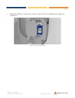
Figure 23 - Turning the nut clockwise
PoE-03 power supply
Use the PoE-03 power supply to power your CFW-2132:
1
Connect the Antenna Power Supply (POE-03) to a dedicated AC power outlet away from running
water, steam and excessive heat.
a
Switch the outlet ON if required.
2
Plug the end of the R45 Ethernet cable that does not have the weather-sealed plug into the R45 socket
named
WALL
on the PoE-03.
3
Fasten the end of the R45 Ethernet cable that has the weather-sealed plug into the antenna power
supply port on the back of the antenna as per instructions in steps 11, 12 and 13 in the previous
section.
4
The lights on the POE-03 injector housing will indicate whether the power supply is connected using
its LED indicator lights. When the POWER LED is red and ANTENNA LED is green, the CFW is correctly
powered and connected.
PoE-03 LED indicators
The table below describes the status of the POWER and ANTENNA LEDs on the PoE injector.
LE D
Statu s
Descr ip tion
POWER
Solid red
Antenna power supply is connected to AC power.
ANTENNA
Solid green
Antenna power supply is connected to AC power and the PoE port is
connected to the CFW.
Table 3 - POE-02 LED indicators

