

© 2020 Carrier
1 / 2
P/N 3100989-EN • REV 012 • ISS 10AUG20
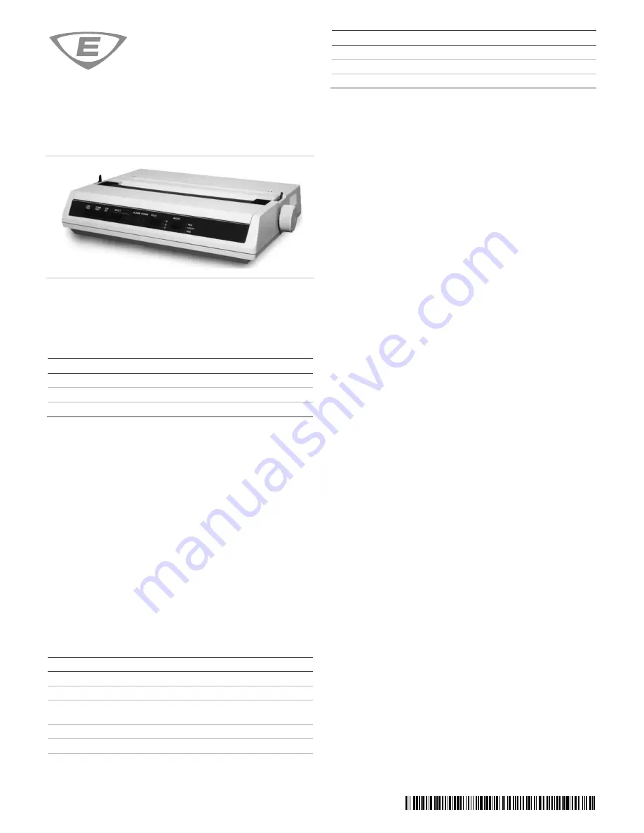
PT-1S Fire Alarm Printer
Installation Sheet
Description
These installation instructions are for the PT-1S printer models listed in
Table 1: Models
Number
Description
PT-1S
Printer, serial/USB, 120 V
PT-1S-220
Printer, serial/USB, 220 V
MIR-PRT/S
Printer, serial/USB, 120 V
PT-1S printers use standard, continuous feed, fanfold paper, and
provide serial and USB cable connections. The paper can be fed from
the rear or from the bottom of the printer.
Each printer is shipped with the following:
• A power cord
• A ribbon cartridge
• A paper separator
• A platen knob
• A CD containing print drivers and user documentation
• A DB-25P connector and hardware for making field wiring
connections to control unit serial ports
• A DTK-DL120/240 surge protective device (220V model only)
Note:
Printer cables are not included with the printer and must be
purchased separately.
Configuring the serial interface
The printer’s serial interface default settings are as follows:
Item
Default settings
Permissible settings
Parity
None
None, Even
Serial Data 7/8 bits 8 bits
8 bits
Protocol
Ready/Busy
Ready/Busy [1],
X-ON/X-OFF [2]
Diagnostic Test
No
No
Busy Line
SSD–
DTR
Baud rate
9600 bps
9600, 4800, 2400, 1200
Item
Default settings
Permissible settings
DSR Signal
Valid
Invalid
DTR Signal
Ready on Power Up
Ready on Power Up
Busy Time
200 ms
200 ms
[1] For supervised printers
[2] For unsupervised printers
Instructions for configuring serial interface settings are provided below.
For more information, refer to the printer manufacturer’s
documentation and the control unit documentation.
Notes
• If the printer and a CDR-3 module share the same serial port
connection, configure both to match the control unit’s serial
interface baud rate and parity settings. For more information, refer
to the control unit documentation.
• Load paper into the printer before performing the instructions
below.
To configure the serial interface:
1. Press and hold the
SELECT
button at the same time you turn on
the printer.
Press the
SELECT
button again to print the current settings.
2. Press the
LINE FEED
button until the printer prints the following:
Serial I/F Parity None
To change the parity setting, press the
TOF SET
button until the
printer prints the required parity.
3. Press the
FORM FEED
button until the printer prints the following:
Serial I/F Protocol Ready/Busy
For an unsupervised printer connection, press the
TOF SET
button
until the printer prints the following:
Serial I/F Protocol X-ON/X-OFF
4. Press the
FORM FEED
button until the printer prints the following:
Serial I/F Busy Line SSD-
Press the
TOF SET
button until the printer prints the following:
Serial I/F Busy Line DTR
5. Press the
FORM FEED
button until the printer prints the following:
Serial I/F Baud rate 9600 bps
To change the baud rate setting, press the
TOF SET
button until
the printer prints the required baud rate.
6. Press the
FORM FEED
button until the printer prints the following:
Serial I/F DSR Signal Valid
Press the
TOF SET
button until the printer prints the following:
Serial I/F DSR Signal Invalid
7. Press the
FORM FEED
button until the printer prints the following:
Serial I/F DSR Signal Ready on Power up
Press the
TOF SET
button until the printer prints the following:
Serial I/F DSR Signal Ready on Select
8. Press the
PITCH
and the
MODE
buttons at the same time to save
your settings and exit Menu Mode.


