


62-61753-21
8-33
j. Install three rotor bolts and bring them snug against
the rotor.
NOTE
The bolts will be torqued later.
k. Remove the guide rods, assemble the remaining
three rotor bolts and and bring them snug against
the rotor.
NOTE
The bolts will be torqued later.
l. Install three stator bolts, each with two washers in
the following locations (See Figure 8-23):
One in five o’clock location
One in eight o’clock location
One in eleven o’clock location
Bring the bolts snug against the stator.
NOTE
The remaining four stator mounting bolts will
be installed and will all be torqued after the fan
cover is installed.
m. Torque the rotor bolts to 79 to 97 Nm (59 to 72 ft-lb)
using an alternating pattern.
NOTE
Mark each rotor bolt after it is torqued to pro-
vide a visual indication that all the bolts are
torqued.
n. Remove the mica shim that is between the stator
and the rotor.
o. Install the fan onto the rotor using the fan mounting
bolt and washer
NOTE
The fan must be installed with blades away
from the engine.
p. Torque the fan bolt to 27to 32 Nm (20 to 24 ft-lb).
q. Feed the wires through the fan cover grommet.
r. Install the fan cover onto the stator and install the
remaining mounting bolts and dual washer sets.
s. Torque the stator/cover mounting bolts to 42 to
52 Nm (31 to 38 ft-lb).
NOTE
Mark each stator bolt after it is torqued to to
provide a visual indication that all the bolts are
torqued
t. Complete reassembly by reversing steps 12 and 10
through 1 of the Removal Instructions. Torque the
upper and lower engine mount bolts to 126 Nm
(93 ft-lb).
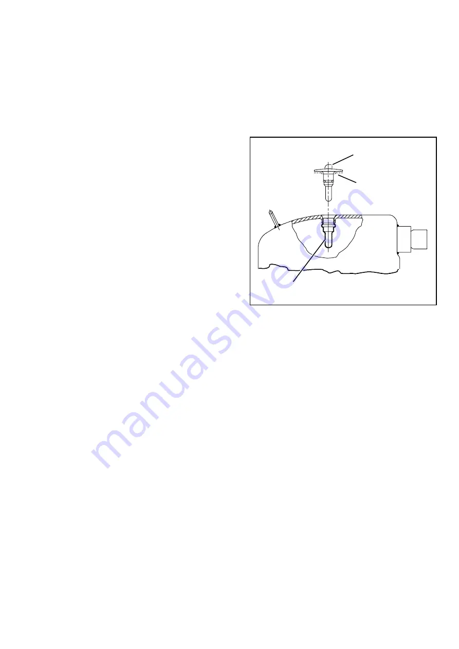
8.7.6 Compressor Discharge
Temperature Sensor
To replace the compressor discharge sensor (see
Figure 8-24) do the following:
a. Ensure the unit is disconnected from the power
source and that SROS is in OFF position.
b. Remove the existing sensor. Clean all silicone seal-
er and dielectric compound from the sensor well.
Ensure well is clean and dry. Top of compressor,
where the sensor seals, must also be clean and dry.
SENSOR WELL
SENSOR
SILICONE BEAD
Figure 8-25. Compressor Discharge
Temperature Sensor
c. Using the syringe supplied with the replacement
sensor, squeeze all of the dielectric compound into
the sensor well.
d. Place a bead of the silicone sealer supplied with the
replacement sensor around the sensor sealing ring.
Insert sensor into the well with the leads parallel to
the suction fitting.
e. Reconnect sensor connector and run a Pretrip to
test.
8.7.7 Sensor Checkout
An accurate ohmmeter must be used to check re-
sistance values shown in Table 8-5 & Table 8-6.
Due to variations and inaccuracies in ohmmeters,
thermometers or other test equipment, a reading within
2% of the chart value would indicate a good sensor. If
a sensor is bad, the resistance reading will usually be
much higher or lower than the resistance values given
in Table 8-5 & Table 8-6.
Two preferred methods of determining the actual test
temperature at the sensor, is an ice bath at 0°C (32°F)
or a calibrated temperature tester.
Содержание NDK33BN0KB
Страница 2: ......
Страница 3: ...OPERATION SERVICE MANUAL for VECTOR 1550 1550 CITY Trailer Refrigeration Units...
Страница 4: ......
Страница 14: ......
Страница 22: ...62 61753 21 1 8 1 5 SAFETY DECALS 62 61343 00 Rev or 62 02139 01 Rev C 62 02143 00 Rev...
Страница 24: ...62 61753 21 1 10 62 60192 00 Rev D...
Страница 30: ...62 61753 21 2 6...
Страница 48: ......
Страница 212: ......
Страница 226: ......
Страница 248: ......
Страница 252: ......
Страница 262: ......
Страница 270: ......


