7
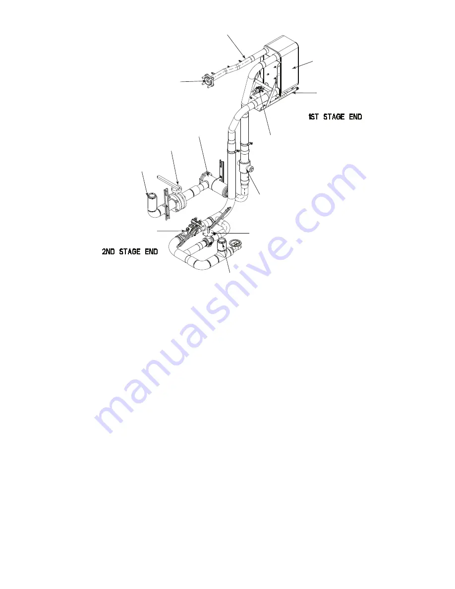
Fig. 3 — Typical 19MV Economizer Assembly Detail
Motor-Compressor
This component maintains system temperature and pressure dif-
ferences and moves the heat-carrying refrigerant from the evapo-
rator to the condenser. The 19MV chiller utilizes a two-stage back
to back direct drive configuration with Interior Permanent Magnet
(IPM) motor and active magnetic bearings.
Variable Frequency Drive (VFD)
The VFD variable frequency is a voltage source design that con-
verts line voltage into PWM (pulse width modulating) motor input
for motor speed and torque control.
Chiller Power Panel
The control panel includes the input and output boards (IOBs),
control transformer, relays, contactors, and circuit breakers. It pro-
vides the power distribution and protection to the electrical com-
ponents installed on chiller and has the following functions:
• Communication with PIC6 touch screen
• Communication with UPS
• Communication with VFD
• Sensor input and outputs
• Actuators control
• Communication with MBC
PIC6 Touch Screen HMI
This panel is the user interface for controlling the chiller and has
the following functions:
• Chiller operation
• Chiller diagnostic
• Chiller status display
• Chiller parameter configuration
• Provide open protocol interface to outside BMS (Building Man-
agement System)
Magnetic Bearing Controller (MBC)
The 19MV compressor uses active magnetic bearings in place of
traditional rolling element bearings, which eliminates the need
for a lubrication system. The magnetic bearings are controlled
by a dedicated Magnetic Bearing Controller (MBC), which com-
municates with the overall system PIC via Modbus communica-
tion. Information available from the MBC on the PIC HMI in-
cludes calibration status, clearance check values, drop counts,
shaft speed, and shaft “orbit” (location) statistics. Due to the
high sampling rate of the MBC as compared to the PIC, the orbit
statistics provide a good approximation of shaft location in real
time. For more detailed bearing information and diagnostics a
direct PC connection can be made to the MBC using an Ethernet
connection from the MBC board. If this is required consult Car-
rier Service Engineering.
UPS
A Uninterrupted Power Supply module (UPS) with Modbus
card is installed within the 19MV power panel. In the event of a
power failure, the UPS provides power to chiller control compo-
nents during power loss events in order to safely bring the levi-
tated shaft to rest on the touch down bearings. If the power inter-
ruption is short, the UPS also supports fast restart of the chiller
upon power restoration. The UPS communicates battery and
power supply status to the PIC through Ethernet (Modbus IP)
communication.
Expansion Control System
The expansion control system consists of two parallel EXVs sup-
ported by a modulating expansion control system valve. The ex-
pansion control system valve can increase or decrease the flow
area quickly and thereby support system stability and range, while
the dual EXV provides precision flow control. The expansion sys-
tem responds primarily to a liquid level sensor which monitors re-
frigerant level within the condenser. Figure 4 shows the liquid lev-
el assembly detail.
ECONOMIZER VENT LINE
BPHX ECONOMIZER
COMPRESSOR ICP INLET
SUPPORT BRACKET
ECONOMIZER EXV
FILTER-DRYER
ISOLATION VALVE
CONDENSER OUTLET
ISOLATION VALVE
EXPANSION CONTROL SYSTEM VALVE (EXCSV)
MAIN EXV
EVAPORATOR INLET
Содержание AquaEdge 19MV
Страница 49: ...49 Fig 46 SIOB...
Страница 50: ...50 Fig 47 IOB2...
Страница 51: ...51 Fig 48 19MV Auxiliary Controls Wiring...
Страница 52: ...52 Fig 49 Motor Bearing Control Board Wiring...


