7–11
T-365
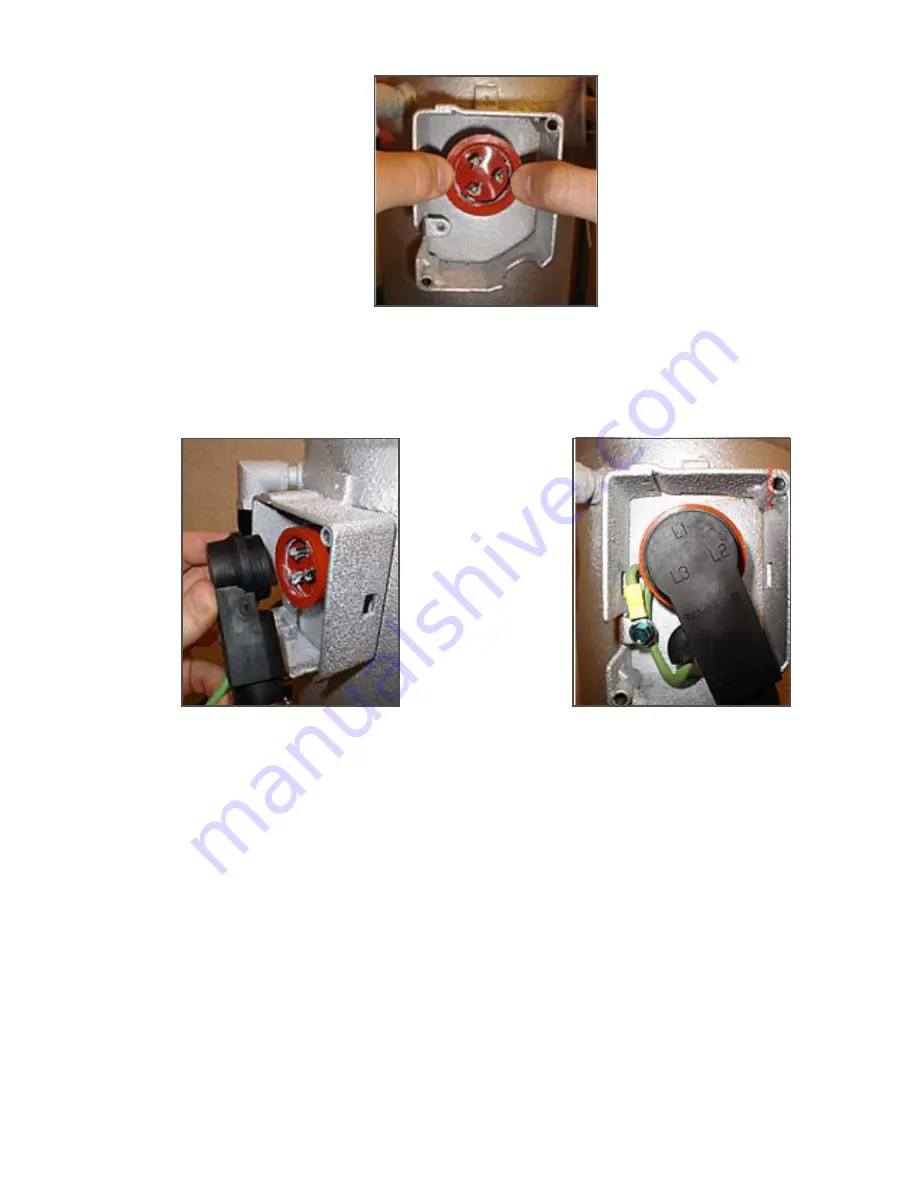
Figure 7.8 Installing Orange Gasket
c. Coat the inside of the power plug (female) connector pins with the Krytox lubricant (
, item #13),
and Insert the plug onto the compressor terminal connections. Make sure, the orange gasket has bot-
tomed out onto the fusite and it fits securely onto the terminal pins while fully inserted into the orange
plug as shown in
and
Figure 7.9 Power Plug Connection
Figure 7.10 Power Plug Secured
19.Connect the green ground wire (
above) to the grounding tab located inside the terminal box of
the compressor using the self tapping grounding screw (
, item #12). Close the compressor termi-
nal box using the terminal cover removed.
20.Evacuate the compressor to 1000 microns (refer to the Operation and Service manual for proper proce-
dures).
If jumper procedure was used in step c, reconnect unit to power and turn on the circuit breaker to again
power the DUV.
21.On completion of the vacuum, remove the magnet and reinstall the DUV coil.
If a jumper was used, turn off the circuit breaker and disconnect power. Reconnect the X1 wire to the black
transformer wire. Reinstall and secure the KA6 wire to the KA plug at the controller.
22.Mid seat service valves, connect power to the unit; turn the unit ON and run it in full cool mode for 10 min-
utes.
23.Initiate code select 59 (unit pump down).
Choosing code select 59, the user will be advised to close (front seat) the Liquid Line Valve (king valve). The
display will flash “CLOSE LLV” and “PrESS EntEr.” Upon closing the valve, select the enter key. Pump down
“PdN” will display on the left with the suction pressure on the right. Upon completion of the pump down the
display will flash between “PdN”“DOnE” and “SHUT OFF.”
24.Front seat the suction and discharge service valve and replace the filter drier.
25.Evacuate the suction side and compressor to 1000 microns.
Содержание 69NT40-561-300
Страница 2: ......
Страница 4: ......
Страница 10: ......
Страница 14: ......
Страница 22: ......
Страница 34: ......
Страница 108: ......
Страница 116: ......
Страница 164: ...T 365 8 2 Figure 8 2 Unit Wiring Diagram Based on Drawing 62ï11755 ...
Страница 165: ...8 3 T 365 Figure 8 3 Wiring Diagram Based on Drawing 62ï11755 ...
Страница 166: ...T 365 8 4 Figure 8 4 Wiring Diagram Based on Drawing 62ï11755 ...
Страница 168: ......
Страница 172: ......
Страница 173: ......


