


62-11785
2–8
2.5.3
Special Features
The following additional special features are incorporated into the Carrier Transicold APX control system:
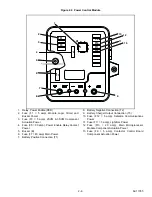
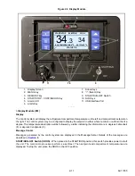
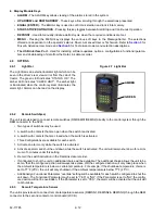
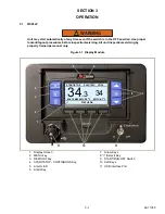
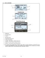
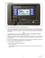
• An easy to read LCD display MessageCenter which clearly displays all required information
• Unit Data and Advanced User selectable Functional Parameters
• Programmable Maintenance Hour Meters
• Bright LED Alarm Light
• Fully Automated Pretrip
• Automated control system Self-test
• DataLink data recorder (uses System date and time)
• Trip Start to record date/time of trip in DataLink data recorder memory
• USB communication for downloading data, upgrading operational software, and Configuration set up
• Functional Parameter locks
• Alarms are stored in control system memory for future reference
• “ATM style” menu system (which reduces keystrokes)
• “Dashboard” display screens which display up to 5 data points simultaneously
• Backlit “Carrier Blue” silicone keypad makes operation easy for drivers
2.5.4
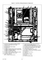
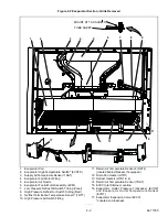
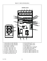
Component Description And Location
The APX control system is an automotive style, decentralized, modular system with CAN bus (Controlled Area
Network) connectivity. Hardware associated with the system includes:
• power control module (PCM -
)
• main microprocessor module (MM)
• stepper valve module (SVM)
• standby and control boxes (
)
• control-box-mounted overload ground fault module (OGF,
)
• control-box-mounted contactor control boards (CCB1 & CCB2,
)
• display module (DM)
NOTICE
Under no circumstances should anyone attempt to repair sealed module internal components.
Should a problem develop with these components, contact your nearest Carrier Transicold
dealer for replacement.
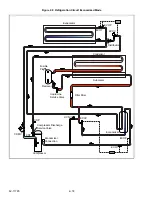
a. Power Control Module
The power control module (PCM - see
) is responsible for distribution of power from the battery to the
system components, when starting, and then from the battery charger to the system components and to the battery
(for charging) once power is available.
The module houses the system relays, low voltage fuses and the DC current transformer (CT). The current
transformer provides a reading of the total 12 VDC system current draw (amps) to the main microprocessor at
terminal 2MM12 (see schematic diagram,
Содержание VECTOR 8100
Страница 2: ......
Страница 4: ......
Страница 12: ...62 11785 viii ...
Страница 16: ...62 11640 12 ...
Страница 18: ...62 11785 ...
Страница 24: ...62 11785 1 6 1 3 SAFETY DECALS ...
Страница 25: ...1 7 62 11785 ...
Страница 26: ...62 11785 1 8 ...
Страница 27: ...1 9 62 11785 ...
Страница 28: ...62 11785 1 10 ...
Страница 30: ...62 11785 ...
Страница 50: ...62 11785 ...
Страница 82: ...62 11785 ...
Страница 96: ...62 11785 4 14 ...
Страница 98: ...62 11785 ...
Страница 129: ...5 31 62 11785 ...
Страница 130: ...62 11785 5 32 ...
Страница 134: ...62 11785 6 4 ...
Страница 138: ...62 11785 ...
Страница 230: ...62 11785 ...
Страница 271: ...8 41 62 11785 ...
Страница 272: ...62 11785 8 42 ...
Страница 274: ...62 11785 ...
Страница 286: ......
Страница 287: ......
Страница 288: ...62 11785 10 8 ...
Страница 292: ......
Страница 293: ......