


7–51
62-11785
P00190
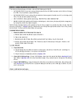
CHECK CONDENSER FAN MOTOR
• ACTIVATION: Normal draw for the condenser fan motors is 0.8 to 3.5 Amps (460 VAC). The circuit tests
outside this range.
• UNIT CONTROL: Pretrip will fail and display “PRETRIP FAIL AND COMPLETED”.
• RESET CONDITION: Auto Reset if Pretrip is started again, or alarm may be manually reset via keypad or
by turning the unit off, then back on again.
NOTE: Follow the steps below until a problem is found. Once a repair or correction has been made, clear the
alarm(s). (See Note 1 in
Section.) Operate the unit through the appropriate modes to see if any active
alarm occurs. Continue with the steps below as necessary.
CORRECTIVE ACTIONS:
460 VAC CIRCUIT
1.
Check Amp Draw of Condenser Fan Motor Circuit
a. With the unit running use a clamp-on ammeter to check the current draw at CDCON on all 3 legs.
Must be within range shown in
for all three legs. If higher than normal draw is read,
the wiring for the motors must be separated, and each motor tested individually.
b. Check fuses for condenser fan motors, F36, F37, and F38. Verify correct fuse, check fuse holder for
damage, see
. Replace fuse as required. Clear alarms, restart and check for repeat
alarm(s).
c. Check voltage at CDCON contacts. Must be within range shown in
for L1-L2, L1-L3,
and L2-L3. Must be within range shown in
for T1-T2, T1-T3, and T2-T3.
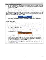
2.
Check Condenser Fan Motors
a. Check condenser fan motors. Verify there is no visual physical damage, and no blockage due to
debris. Remove and replace if required.
b. With the unit off, visually check fan motors and fan blades. Verify there is no visual physical
damage, no blockage to fan blades, and blades spin freely. Remove and replace if required.
c. With the unit off, check the resistance of the condenser fan motor windings. See
for
correct resistance. Resistance (Ohms) must be in range. No continuity from any high voltage lead to
ground.
3.
Check Condenser Fan Motor Connections
- Inspect high voltage connections at the condenser fan
motors. Verify there is no corrosion, water damage or burning / discoloration. Remove, repair, or replace
if required.
4.
Verify Accuracy of AC Current Sensor
a. Put microprocessor in PC Mode. Refer to Note 2 in
Section. Must have 0 AC1 Amps and 0
AC2 Amps in Unit Data.
b. Use a clamp-on ammeter to measure current draw of all 3 legs of the T side of PSCON/PSCON2.
Meter reading should be the same as Unit Data: Compare meter reading to Unit Data in PC Mode.
Compare meter reading to Unit Data with unit under load.
Содержание VECTOR 8100
Страница 2: ......
Страница 4: ......
Страница 12: ...62 11785 viii ...
Страница 16: ...62 11640 12 ...
Страница 18: ...62 11785 ...
Страница 24: ...62 11785 1 6 1 3 SAFETY DECALS ...
Страница 25: ...1 7 62 11785 ...
Страница 26: ...62 11785 1 8 ...
Страница 27: ...1 9 62 11785 ...
Страница 28: ...62 11785 1 10 ...
Страница 30: ...62 11785 ...
Страница 50: ...62 11785 ...
Страница 82: ...62 11785 ...
Страница 96: ...62 11785 4 14 ...
Страница 98: ...62 11785 ...
Страница 129: ...5 31 62 11785 ...
Страница 130: ...62 11785 5 32 ...
Страница 134: ...62 11785 6 4 ...
Страница 138: ...62 11785 ...
Страница 230: ...62 11785 ...
Страница 271: ...8 41 62 11785 ...
Страница 272: ...62 11785 8 42 ...
Страница 274: ...62 11785 ...
Страница 286: ......
Страница 287: ......
Страница 288: ...62 11785 10 8 ...
Страница 292: ......
Страница 293: ......