


4–23
T-372
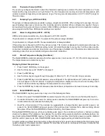
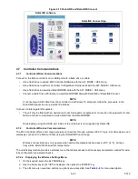
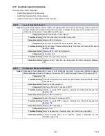
Figure 4.15 DataLINE and DataLINE Connect
4.7 Controller Communications
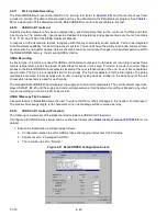
4.7.1
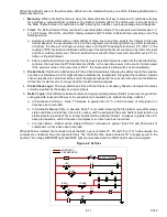
Controller Wired Communications
Connect to the ML5 controller’s micro USB port with a flash drive or cable:
• Use a flash drive to upload ML5 Controller Software with the ALT. MODE > USb menu.
• Use a flash drive to perform Controller Configuration / Setup tasks with the ALT. MODE > USb menu.
• Use a flash drive to download DataCORDER data with the ALT. MODE > USb menu.
• Connect a cable from a PC/laptop to view DataCORDER data with DataLINE or DataLINE Connect.
NOTE
If connecting a USB cable from the controller to a Windows 10 computer, follow the procedure in the
DataLINE manual to set up a static IP address.
Connect via Interrogator Receptacle:
• The unit may be fitted with an optional external interrogator receptacle for connection of equipment for cali
-
bration and also to download recorded data from the DataCORDER.
NOTE
Downloading using the USDA port inside of the container is not supported by DataLINE.
4.7.2
Controller Wireless Communications
The ML5 controller offers short range wireless connectivity through wireless 802.11 b/g/n. A mobile device can
wirelessly connect to the ML5 controller using the DataLINE Connect app.
NOTE
Wireless connectivity may only operate when ambient temperatures are above -20°C (-4°F). Connec
-
tivity will be intermittent below this temperature.
The unit display module provides a wireless menu that allows access to all necessary parameters needed for wire
-
less configuration and status checks.
4.7.2.a Displaying the Wireless Settings Menu
1. On the keypad, press the ALT. MODE key.
2. Use the Arrow keys until "nEt" is displayed, then press the “ENTER” key.
3. The nEt menu is now active and menu options are accessible. See
for menu description.
DataLINE software
DataLINE Connect App
Содержание PrimeLINE 69NT40-571-001
Страница 2: ......
Страница 4: ......
Страница 14: ......
Страница 36: ......
Страница 110: ......
Страница 116: ......
Страница 171: ...8 1 T 372 SECTION 8 ELECTRICAL WIRING SCHEMATIC AND DIAGRAMS Figure 8 1 Legend Standard Unit Configuration ...
Страница 172: ...T 372 8 2 ELECTRICAL WIRING SCHEMATIC AND DIAGRAMS Figure 8 2 Schematic Diagram Based on Drawing 62 11957 ...
Страница 176: ......
Страница 178: ......
Страница 180: ......
Страница 184: ......
Страница 185: ......