


T-372
4–12
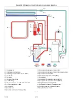
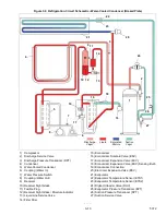
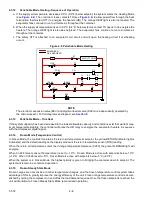
The EEV and DUV are independently operated by the microprocessor. Complete schematics and legends are
located in Section 8.
Defrost will terminate when the DTS reading rises above one of two model number configurable options selection,
either an upper setting of 25.6°C (78°F) which is default or lower setting of 18°C (64°F). When the DTS reading
rises to the configured setting, the de-icing operation is terminated.
4.3.22
Defrost Related Settings
DTS Failure
When the return air temperature falls to 7°C (45°F), the controller ensures that the defrost temperature sensor
(DTS) reading has dropped to 10°C or below. If it has not, it indicates a failed DTS. A DTS failure alarm is triggered
and the defrost mode is operated by the return temperature sensor (RTS). Defrost will terminate after 1 hour. If the
DTS fails to reach is termination setting, the defrost terminate after 2 hours of operation.
Defrost Timer
If CnF23 is configured to “SAv” (save), then the value of the defrost interval timer will be saved at power down and
restored at power up. This option prevents short power interruptions from resetting an almost expired defrost inter
-
val, and possibly delaying a needed defrost cycle. If the save option is not selected the defrost timer will re-initiate
and begin recounting.
If CnF11 is model number configured to OFF the operator may choose “OFF” as a defrost interval option.
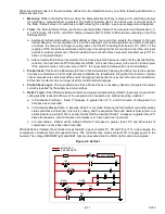
If defrost does not terminate correctly and temperature reaches the set point of the Heat Termination Thermostat
(HTT) 54°C (130°F), the HTT will open to de-energize the heaters (AL259 & AL260). If the HTT does not open and
termination does not occur within two hours, the controller will terminate defrost. AL260 will be activated to inform
of a possible DTS failure.
4.3.23
Protection Mode - Evaporator Fan Operation
Opening of an evaporator fan internal protector will shut down the unit.
4.3.24
Protection Mode - Failure Action
Function code Cd29 may be operator set to select the action the controller will take upon a system failure. The fac
-
tory default is full system shutdown. See
4.3.25
Protection Mode - Generator Protection
Function codes Cd31 (Stagger Start, Offset Time) and Cd32 (Current Limit) may be operator set to control the start
up sequence of multiple units and operating current draw. The factory default allows on demand starting (no delay)
of units and normal current draw. See
.
4.3.26
Protection Mode - Compressor High Temperature Protection
The controller continuously monitors compressor discharge pressure and temperature, and suction pressure. If
discharge pressure or temperature rises above the allowed limit or suction pressure falls below the allowed limit,
the compressor will be cycled off and on every 3 minutes. Condenser and evaporator fans will continue to operate
during the compressor off cycle.
If high compressor dome temperature occurs, as measured by the CPDS, the controller will allow additional refrig
-
erant to be released into the system in order to provide cooling to the evaporator coil and compressor dome. The
controller is alerted to high compressor dome temperatures via the CPDS when ambient temperature is greater
than 43.3°C (110°F), return air temperature is less than -17.5°C (0.5°F) and the compressor discharge temperature
is greater than 117.7°C (244°F). Dome temperature control logic will disengage when return air temperature and
ambient temperature return to allowed limits or when the compressor turns off.
4.3.27
Protection Mode - Compressor Low Pressure Protection
If the suction pressure low limit is triggered, the DUV will energize to raise the suction pressure.
4.3.28
Protection Mode - Perishable Mode System Pressure Regulation
In Perishable Mode, system pressures may need to be regulated at ambient temperatures of 20°C (68°F) and
below. Once below this ambient temperature, the condenser fan may cycle on and off based on limits imposed for
discharge pressure. For extremely cold ambient temperatures, -18°C (0°F), heater cycling may occur within normal
system operation based on discharge pressure limits.
Содержание PrimeLINE 69NT40-571-001
Страница 2: ......
Страница 4: ......
Страница 14: ......
Страница 36: ......
Страница 110: ......
Страница 116: ......
Страница 171: ...8 1 T 372 SECTION 8 ELECTRICAL WIRING SCHEMATIC AND DIAGRAMS Figure 8 1 Legend Standard Unit Configuration ...
Страница 172: ...T 372 8 2 ELECTRICAL WIRING SCHEMATIC AND DIAGRAMS Figure 8 2 Schematic Diagram Based on Drawing 62 11957 ...
Страница 176: ......
Страница 178: ......
Страница 180: ......
Страница 184: ......
Страница 185: ......