background image

62-10848

3-6

3.9

Microprocessor Configuration

CAUTION

!

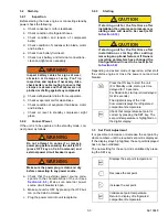
If starting the unit for the first time after
installation or starting after adding/
removing an optional feature or if Owners
operating parameters have changed, the
Configuration will need to be reset.

3.9.1

Road Only Functional Settings

The procedure for adjusting the functional parameters
is as follows:

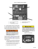
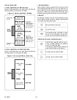
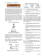
1. The temperature display is selectable between

Fahrenheit and Celsius. Units are configured for
Celsius from the factory. To set the display to
Fahrenheit, the selection jumper must be
removed and discarded. See 

Figure 2.6

.

NOTE

The board contains another set of pins simi-
lar to the Degrees C/Degrees F selection
jumper, marked as J1. This jumper is not
used for unit operation, but it is used during
the microprocessor controller manufacturing
process. 

DO NOT CONNECT THE J1 PINS

TOGETHER

.

2. Press the OFF key to shut down the unit.

NOTE

The following steps must be performed with
the unit OFF.

3. Press the Defrost and ON keys simultaneously

in order to display parameters.

NOTE

If no buttons are pressed within 5 seconds of
pressing the Defrost and ON keys or modify-
ing parameters, the Cab Command reverts
to refrigerated compartment temperature
display and the configuration procedure is
aborted.

4. Press the + or - keys to modify parameters.

a. The defrost duration parameter is displayed.

This setting determines the length of time in
minutes the unit will remain in defrost once
defrost is initiated. The defrost duration can
be selected by scrolling through available
options (10, 20, 25, 30 or 45 minutes) using
the (+) or (-) keys. Selection MUST be vali-
dated by pressing the SET key.

b. The defrost interval parameter is displayed

next. This setting determines the time
between defrosts in hours. The defrost inter-
val can be selected by scrolling through
available options (0, 1, 1.5, 2, 2.5, 3, 4, 5, 6
hours) using the (+) or (-) keys. Selection
MUST be validated by pressing the SET key.

5. Press the SET key to validate modified settings.

6. Press the ON key to start-up the unit.

NOTE

The following steps must be performed with
the unit OFF.

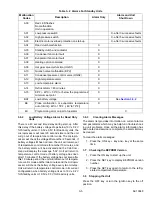
7. Press the + key, then - key, then Defrost keys.

All keys should be held momentarily after press-
ing in the correct sequence.

NOTE

If no buttons are depressed within five sec-
onds of pressing the ON key or modifying
parameters, the Cab Command reverts to
refrigerated compartment temperature dis-
play and the configuration procedure is
aborted.

8. Press the + or - keys to modify parameters.

a. The minimum set point parameter is dis-

played. The minimum set point can be
selected by scrolling through available
options [- 20°F (- 28.9°C), - 4°F (- 20°C),
32°F (0°C)] using the (+) or (-) keys. Factory
setting is - 32°F (0°C). Selection MUST be
validated by pressing the SET key.

b. The null mode differential temperature is dis-

played next. This setting determines the
temperature difference between refrigerated
compartment temperature and set point that
controls compressor cycling. The differential
can be selected by scrolling through avail-
able options [1.8°F (1°C), 3.6°F (2°C), or
5.4°F (3°C)] using the (+) or (-) keys. Factory
setting is 3.6°F (2°C). Selection MUST be
validated by pressing the SET key.

c. The ON/OFF (Continuous airflow) parameter

for the evaporator fan is displayed next. This
feature determines whether the evaporator
fan is on or off when the unit cycles off upon
reaching set point. The factory setting is
OFF. Change setting by using the (+) or (-)
keys. Selection MUST be validated by
pressing the SET key.

d. The return air temperature will be displayed

after the above sequence.

9. Press the SET key to validate modified settings.

Содержание INTEGRA 30S

Страница 1: ...Truck Refrigeration EVAPORATOR CONDENSER TXV TXV BULB RECEIVER Operation and Service Manual for INTEGRA 30S Truck Refrigeration Units Beginning with S N PB 225225 62 10848 Rev D ...

Страница 2: ......

Страница 3: ...Operation and Service Manual for INTEGRA 30S Truck Refrigeration Units Beginning with S N PB 225225 2018 Carrier Corporation Printed in USA June 2018 ...

Страница 4: ......

Страница 5: ... 8 Receiver 2 3 2 3 9 High Pressure Switch HP1 2 4 2 3 10 Condenser Pressure Control Switch HP2 2 4 2 4 EVAPORATOR SECTION 2 4 2 4 1 Thermostatic Expansion Valve 2 4 2 4 2 Compressor Pressure Regulating Valve CPR 115V Only 2 4 2 4 3 Defrost Termination Thermostat DTT 2 4 2 4 4 Quench Valve BPV 2 4 2 4 5 Evaporator 2 4 2 4 6 Low Pressure Switch LP 2 4 2 5 SYSTEM OPERATING CONTROLS AND COMPONENTS 2 ...

Страница 6: ...CE AND ADJUSTMENT 5 3 5 2 1 Standby Motor Compressor V Belt 5 3 5 3 INSTALLING R 134A MANIFOLD GAUGE SET 5 3 5 3 1 Preparing Manifold Gauge Hose Set For Use 5 3 5 3 2 Connecting Manifold Gauge Hose Set 5 3 5 3 3 Removing the Manifold Gauge Set 5 4 5 4 REMOVING THE REFRIGERANT CHARGE 5 4 5 4 1 Refrigerant Removal From a Non Working Compressor 5 4 5 5 REFRIGERANT LEAK CHECKING 5 4 5 6 EVACUATION AND...

Страница 7: ...8 EVAPORATOR COIL CLEANING 5 10 5 19 CONDENSER COIL CLEANING 5 10 TROUBLESHOOTING 6 1 6 1 INTRODUCTION 6 1 6 2 REFRIGERATION 6 3 6 2 1 Unit Will Not Cool 6 3 6 2 2 Unit Runs but has Insufficient Cooling 6 3 6 2 3 Unit Operates Long or Continuously in Cooling 6 3 6 2 4 Unit Will Not Heat or Heating Insufficient 6 3 6 2 5 Defrost Malfunction 6 3 6 2 6 Abnormal Pressure Cooling 6 4 6 2 7 Abnormal Pre...

Страница 8: ......

Страница 9: ...ier commonly used to clean air Actuator That portion of a regulating valve that converts mechanical fluid thermal energy or electrical energy into mechanical motion to open or close valve seats Adiabatic Compression Compressing refrigerant gas without removing or adding heat Adsorbent Substance which has property to hold molecules of fluids without causing a chemical or physical change Adsorption ...

Страница 10: ...an air conditioning or heat pump system The compressor maintains ade quate pressure to cause refrigerant to condense and flow in sufficient quantities to meet the cooling requirements of the system Damper Valve for controlling airflow Found in duct work movable plate opens and closes to control airflow Can be manually or automatically controlled to regulate airflow to desired system zones Decibel ...

Страница 11: ...insulation Heat Exchanger A device for the transfer of heat energy from the source to the conveying medium with the latter often being air or water Most common combinations are Refrigerant to air or refrigerant to water DX water to air hydronic steam to air steam to water Humidity The total amount of moisture in air Relative humidity RH is the amount of moisture in air relative to its total capabi...

Страница 12: ...ll of today s HVAC and R equipment requiring motors over 1 10hp An upgrade from Shaded Pole design motors See Capacitor Motor Running Psychrometer Either a sling type or electronic Instrument used to determine wet bulb temperatures and relative humidity Combining RH with dry bulb temperature will yield total heat Range Pressure or temperature settings of a control change within limits Receiver Hea...

Страница 13: ... BTUs per hour Vacuum Reduction in pressure below atmospheric pressure Vacuum Control Systems In some air conditioning systems vacuum is used to operate dampers and controls in system Vacuum Pump Special high efficiency device pump used create deep vacuum within an AC R systems for the purpose of moisture removal dehydration removal of non condensibles and can also be used as well for leak checkin...

Страница 14: ...62 11868 1 8 ...

Страница 15: ...the road and standby modes The unit may start at any time When performing any check of the system make certain all circuit breakers are turned off and battery power supply is disconnected Be sure power is turned off before working on motors controllers solenoid valves and electrical control switches Tag circuit breaker and vehicle ignition to prevent accidental energizing of circuit Do not bypass ...

Страница 16: ...equirements dictate Press the OFF key on the Cab Com mand and disconnect the power plug WARNING Inspect battery cables for signs of wear abrasion or damage at every pre trip inspection and replace if necessary Also check battery cable routing to ensure that clamps are secure and that cables are not pinched or chafing against any components WARNING Do not attempt to connect or remove power plug bef...

Страница 17: ...N Do not damage or over tighten the enclosing tube assembly Place all parts in the enclosing tube in proper sequence in order to avoid premature coil burn out CAUTION Observe proper polarity when installing battery negative battery terminal must be grounded CAUTION Under no circumstances should a technician electrically probe the processor at any point other than the connector terminals where the ...

Страница 18: ......

Страница 19: ... pressure control valve On road standby units the condensing section also houses the standby compressor control box and rectifier and houses the transformer assembly see Figure 2 2 and Figure 2 5 2 3 1 Condenser Subcooler The condenser is of the tube and fin type and acts as a heat exchanger in which the compressed refrigerant gas is condensed into a liquid and lowered in tempera ture Air movement...

Страница 20: ...tandby Compressor See Table 1 1 7 Control Box 8 Filter Drier 9 Liquid Line Check Valve 10 Sight Glass 11 Receiver 12 Discharge Manifold 13 Hot Gas Solenoid Valve HGS1 14 Condenser Pressure Control Switch HP2 15 Frame 16 High Pressure Switch HP1 17 Condenser Pressure Control Valve HGS2 Cab Command 1 2 3 4 5 6 7 8 9 10 11 12 13 14 15 16 17 ...

Страница 21: ...n the cool mode and the compressor discharge gas is delivered to the condenser In the cool mode heat is removed from the air inside the truck body and rejected to the surrounding air With the solenoid coil energized the valve is in the heat mode and the compressor dis charge gas is diverted to the evaporator and rejected to the air inside the truck body 2 3 6 Compressor The compressor withdraws re...

Страница 22: ...ly See Figure 2 3 The CPR valve is installed on the suction line of the standby compressor to regulate the suction pressure entering the compressor The CPR valve is set to limit the maximum suction pressure For CPR settings refer to Section 2 6 2 The suction pressure is controlled to avoid overloading the electric motor during high refrigerated compartment temperature operation To adjust the CPR v...

Страница 23: ...lutch Time Delay Relay CT Single Phase Only 5 Clutch Relay CR 6 Motor Contactor MC 7 Overload Relay OL 230V Only 8 Diode 9 Rectifier Bridge Assembly BR 10 Filter Capacitor C1 11 Start Relay STBR 12 Run Capacitor CR 13 Start Capacitor CS 14 Heat sink rectifier bridge 1 2 3 4 5 6 7 8 9 10 11 12 12 13 13 14 115 1 60 230 1 60 230 1 60 115 1 60 ...

Страница 24: ...cessor Module 1 Connector 2 Road Relay RR 3 12 Volt dc Road Connection 4 12 Volt dc Standby Connection 5 Standby Relay SR 6 C or F Temperature Selector 7 Microprocessor PC 8 Road Fuse F1 30A 9 Overload Relay OL 25A 115V Only 1 2 3 4 5 6 7 8 9 ...

Страница 25: ...ntrol requirements dictate The control system consists of the Cab Command located in the driver s section Figure 2 8 and the micro processor module Figure 2 6 located in the control box The Carrier Transicold Control System incorporates the following features a Control return air temperature to tight limits by providing refrigeration control heat and defrost to ensure conditioned air delivery to t...

Страница 26: ...ns at 130 psig 10 psi 9 bars Closes at 175 psig 10 psi 12 bars Refrigerant charge Refer to Table 1 1 Compressor Pressure Regulating Valve CPR 115V only 19 1 psig 1 3 Bar Thermostatic Expansion Valve TXV Superheat setting 4 C 7 2 F at refrigerated compartment temperature of 20 C 0 F Low Pressure switch LP Opens at 13 23 in HG 6 in HG 0 45 0 2 bar Closes at 6 5 psig 3 psig 0 44 0 2 bar Quench Thermo...

Страница 27: ...2 4 Fan Motors Data Evaporator Fan Motor EFM Condenser Fan Motor CFM Bearing Lubrication Factory Lubricated Bearing Lubrication Factory Lubricated Horsepower 0 1 kw Operating Amps 10 8 amps Operating Amps 10 amps Speed 2800 3000 rpm Speed 3300 rpm Table 2 5 Standby Motor Ratings Voltage Type of Connection Phase kW HP Speed Contractor Data MRA LRA 115 1 60 Δ 1 1 5 2 1745 rpm 18 3 132 5 208 1 60 Δ 1...

Страница 28: ... Excessive current draw evaporator and condenser fan motors Electronic relay YES Self protected opening Excessive compressor discharge pressure Automatic reset of High pressure switch HP1 YES Cutout 355 psig 24 5 bar Excessive current draw standby clutch Fuse F3 a NO Opens at 5 A 12 V Excessive current draw unit in standby operation Standby fuse F2 a NO Opens at 30 A 12 V Excessive current draw un...

Страница 29: ...te of refrigerant towards the evaporator in order to obtain maximum use of the evaporator heat transfer surface The evaporator tubes have aluminum fins to increase heat transfer therefore heat is removed from the air circulating through the evaporator This cold air is circu lated throughout the truck to maintain the cargo at the desired temperature The transfer of heat from the air to the low temp...

Страница 30: ...SWDQGE RPSUHVVRU CRQGHQVHU SXEFRROHU RHFHLYHU FLOWHU ULHU 6 JKWJODVV TXV EYDSRUDWRU DHIURVW EOHPHQW RQGHQVHU 3UHVVXUH RQWURO 9DOYH 6 HP1 TXV ETXDOL HU LQH QXHQFK TKHUPRVWDW BPT SXFWLRQ KDUJLQJ 3RUW DLVFKDUJH CKDUJLQJ PRUW DLVFKDUJH LLTXLG LLTXLG QMHFWLRQ LQH HRW DV LQH SXFWLRQ QH QXHQFK 9DOYH BPV KLQJ 9DOYH CPR 115V OQO CKHFN VDOYH 5RDG RPSUHVVRU ...

Страница 31: ...SDUDWRU 5RDG RPSUHVVRU 6WDQGE RPSUHVVRU RQGHQVHU 6XEFRROHU 5HFHLYHU LOWHU ULHU 6LJKWJODVV 7 9 4XHQFK 9DOYH 39 YDSRUDWRU HIURVW OHPHQW 7 9 TXDOL HU LQH 4XHQFK 7KHUPRVWDW 37 6XFWLRQ KDUJLQJ 3RUW LVFKDUJH KDUJLQJ 3RUW 3 LQJ 9DOYH 35 9 2QO KHFN 9DOYH LVFKDUJH LTXLG LTXLG QMHFWLRQ LQH RW DV LQH 6XFWLRQ QH RQGHQVHU 3UHVVXUH RQWURO 9DOYH 6 ...

Страница 32: ......

Страница 33: ... data For further details on digital message display see Sec tion 3 6 3 1 3 Cab Command The Cab Command is mounted in the cab and allows the driver to carry out the control operations Start up and shut down the unit Automatic start up in road or standby mode Adjust the set point Defrost The driver can display the refrigerated compartment temperature and see whether the set point is being maintaine...

Страница 34: ...ble the opera tor to activate various functions display operating data and modify operating parameters Unit data and function modification keys SETPOINT Setpoint 9qF 5_C Setpoint differential of 1 8qF 1qC 3 6qF 2qC or 5 4qF 3_C Setpoint differential of 1 8qF 1qC 3 6qF 2qC or 5 4qF 3_C Setpoint 9qF 5_C Green LED flashing 3 Hz Green LED flashing 0 5 Hz Steady green LED Steady green LED Green LED fla...

Страница 35: ...ection 2 6 3 Make sure external power source circuit breaker is open b Make sure unit is OFF by pressing the OFF but ton on the Cab Command c Plug the power cord into unit receptacle 3 2 3 Starting CAUTION If starting unit for the first time after installation the compressor pressure reg ulating valve will need to be reset refer to Section 5 14 CAUTION If starting unit for the first time after ins...

Страница 36: ...ge The message will remain displayed until the malfunction is corrected If standby power is connected and the malfunction is such that standby operation can be allowed the unit will start in the standby mode 3 6 1 Accessing Alarm Messages To access the alarm messages 1 Press the SET key for five seconds This enables access to alarm messages 2 In the event of more than one alarm press the or keys t...

Страница 37: ... problems Once all the alarm information has been noted and service is complete the alarm list may be cleared To clear the alarm messages 1 Press the ON key key and key at the same time 3 7 Checking the EEPROM Version 1 Press the ON key to start up the unit 2 Press the SET key to display EEPROM version number 3 Press the SET key again to return to the refrig erated compartment temperature 3 8 Stop...

Страница 38: ...ed next This setting determines the time between defrosts in hours The defrost inter val can be selected by scrolling through available options 0 1 1 5 2 2 5 3 4 5 6 hours using the or keys Selection MUST be validated by pressing the SET key 5 Press the SET key to validate modified settings 6 Press the ON key to start up the unit NOTE The following steps must be performed with the unit OFF 7 Press...

Страница 39: ... NOTE If no buttons are depressed within five sec onds of pressing the ON key or modifying parameters the Cab Command reverts to refrigerated compartment temperature dis play and the configuration procedure is aborted 8 Press the or keys to modify parameters a The minimum set point parameter is dis played The minimum set point can be selected by scrolling through available options 20 F 28 9 C 4 F ...

Страница 40: ......

Страница 41: ...the certainty the unit will enter the null mode If the continu ous air flow parameter is set to ON the evapo rator fans will continue to operate with all other components OFF If the continuous air flow parameter is OFF the evaporator fans and all other components will be OFF A 5 minute delay is required before restart is allowed d If temperature increases during the null mode the unit will restart...

Страница 42: ...onger displayed During defrost the evaporator fans shut down and operation of the condenser fan is controlled by the microprocessor The end of the cycle is controlled by the opening of the defrost termination thermostat See Section 2 8 2 for a description of the refrigeration cir cuit during heat and defrost 4 3 Minimum Off Time Once the unit has cycled off it will remain off for the minimum off t...

Страница 43: ...ntal laws U S A EPA section 608 5 1 Maintenance Schedule Regular servicing is required in order to optimize the life and reliability of your unit The recommended scheduled maintenance intervals and categories are provided in Table 5 1 while descriptions of the service procedures to be carried out under each category are provided in Table 5 2 Refrigerant Type R 134A Road compressor oil type The roa...

Страница 44: ...rator and condenser Section 5 18 and Section 5 19 2 Replace the road and standby compressor belt s 3 Check and if required replace the filter drier Section 5 10 4 Check the operation of cab command 5 Check the defrost Cut in Fan shut down Cut out Defrost water drain Service C 1 Check the operation of the evaporator and condenser fans Change the condenser evaporator motor brushes 2 Change the compr...

Страница 45: ... belt tension Tighten the motor retaining bolts 5 3 Installing R 134A Manifold Gauge Set A R 134a manifold gauge hose set with self sealing hoses is required for service of models covered within this manual The manifold gauge hose set is available from Carrier Transicold Carrier Transicold P N 07 00294 00 which includes items 1 through 6 Figure 5 3 To perform service using the manifold gauge hose ...

Страница 46: ... a compressor that is not operational do the following a Attach a manifold gauge set as shown in Figure 5 3 b Recover refrigerant with a refrigerant recovery system c Service or replace components as required and leak check the entire system See Section 5 5 5 5 Refrigerant Leak Checking A refrigerant leak check should always be performed after the system has been opened to replace or repair a comp...

Страница 47: ...lternate sources of heat may be used to raise system temperature d Additional time may be saved during a complete system pump down by replacing the filter drier with a section of copper tubing and the appropri ate fittings Installation of a new filter drier may be performed during the charging procedure Figure 5 4 Vacuum Pump Connection 1 Refrigerant Recovery Unit 2 Refrigerant Cylinder 3 Evacuati...

Страница 48: ...lined in step d above In this case vapor charge remaining refrigerant through the suction service port See Section 5 7 3 e When refrigerant cylinder scale indicates that the correct charge has been added close the liquid line valve on cylinder and backseat the king valve f Replace all valve caps g Start unit and check for non condensables 5 7 3 Adding a Partial Charge NOTE When partially charging ...

Страница 49: ...gh Pressure HP1 and Condenser Pres sure HP2 Switches 5 11 1 Removing Switch a A Schrader valve is located under each switch to allow removal and installation without remov ing the refrigerant charge b Remove switch and test in accordance with Section 5 11 2 c Replace or reinstall switch 5 11 2 Checking Pressure Switch WARNING Do not use a nitrogen cylinder without a pressure regulator See Figure 5...

Страница 50: ...ecessary to remove the refrigerant charge to replace the coil see Figure 5 7 a Remove coil snap cap voltage plate and coil assembly Disconnect leads and remove coil junction box if necessary b Verify coil type voltage and frequency This information appears on the coil voltage plate and the coil housing c Place new coil over enclosing tube and then install voltage plate and snap cap Figure 5 7 Hot ...

Страница 51: ... Remove insulation from expansion valve bulb and then remove bulb from suction line c Loosen flare nut and disconnect equalizer line from expansion valve d The txv bulb is located below the center of the suction line This area must be clean to ensure positive bulb contact Strap bulb to suction line and insulate both e Braze the equalizer tubes to expansion valve f Evacuate dehydrate and recharge u...

Страница 52: ...sconnected When welding is performed on other areas of the truck and van the welder ground con nection MUST be in close proximity to the area being welded It is also a good practice to remove both battery cables before welding on either the unit frame or the truck to prevent possible damage to other components such as the alternator and voltage regulator 5 18 Evaporator Coil Cleaning The use of re...

Страница 53: ... 0 25 in Hg 18 28 2 3 in Hg 0 16 in Hg 16 27 0 8 in Hg 0 06 in Hg 14 26 0 03 in Hg 0 02 in Hg 12 24 1 1 0 08 10 23 1 9 0 13 8 22 2 8 0 19 6 21 3 6 0 25 4 20 4 5 0 31 2 19 5 5 0 38 0 18 6 5 0 45 2 17 7 5 0 52 4 16 8 5 0 59 6 14 9 6 0 66 8 13 10 8 0 75 10 12 12 0 0 83 12 11 13 1 0 90 14 10 14 4 1 00 16 9 15 7 1 08 18 8 17 1 1 18 20 7 18 5 1 28 22 6 19 9 1 37 24 4 21 4 1 48 26 3 22 9 1 58 28 2 24 5 1...

Страница 54: ... 64 1 4 42 70 21 71 2 4 91 75 24 78 7 5 43 80 27 86 8 5 99 85 29 95 4 6 58 90 32 104 4 7 20 95 35 114 1 7 87 100 38 124 3 8 58 105 41 135 1 9 32 110 43 146 5 10 11 115 46 158 6 10 94 120 49 171 3 11 82 125 52 184 8 12 74 130 54 198 9 13 72 135 57 213 8 14 74 140 60 229 4 15 83 145 63 245 8 16 95 150 66 263 0 18 15 Table 5 4 R 134A Temperature Pressure Chart Continued Temperature Pressure F C Psig ...

Страница 55: ...Table 6 1 Alarm Indications Alarm Description Corrective Action Reference Section A00 No Malfunction All components functioning normally A01 Low Pressure Switch LP or High Pressure Switch HP1 Open Road Unit undercharged 5 7 1 Liquid line filter drier restricted 5 10 1 TXV strainer plugged with foreign material ice 5 15 TXV malfunction 5 15 Verify operation of evaporator fans Failed switch 5 11 2 A...

Страница 56: ...nits Only Out of Range High Temperature Unit out of range for 15 minutes Verify cooling operation of unit 5 13 1 Hot gas solenoid open Verify setting A13 Standby Units Only Out of Range Low Temperature Unit out of range for more than 15 minutes Verify heating operation of unit 3 9 Heating option not active Set configuration A14 Standby Units Only Defrost Cycle 45 minutes Unit terminated defrost af...

Страница 57: ...Refrigeration system Abnormal pressure 6 2 6 Temperature microprocessor malfunction 6 2 8 Compressor Defective 5 9 6 2 4 Unit Will Not Heat or Heating Insufficient Refrigeration Abnormal pressure 6 2 6 Temperature microprocessor malfunction 6 2 8 Hot gas solenoid malfunction HGS1 5 13 Compressor Compressor drive clutch defective Check Compressor defective 5 9 6 2 5 Defrost Malfunction Automatic de...

Страница 58: ...e when unit is operating Compressor defective 5 9 Hot gas solenoid malfunction 5 13 6 2 7 Abnormal Pressure Heating High discharge pressure Overcharged system 5 7 1 Condenser fan or HP2 pressure switch defective 5 11 Non condensibles in system 5 8 Condenser motor fan defective 5 12 Low discharge pressure Compressor defective 5 9 Hot gas solenoid valve malfunction 5 13 Low suction pressure Low refr...

Страница 59: ... open by foreign material 5 15 Fluctuating suction pressure Improper bulb location or installation 5 15 Insulation missing from sensing bulb Replace Low superheat setting 5 15 2 High superheat Expansion Valve setting 5 15 2 6 2 12 Malfunction Hot Gas Solenoid or Condenser Pressure Regulating Valve Valve does not function properly No power to valve Check Improper wiring or loose connections Check V...

Страница 60: ......

Страница 61: ...dule or Cab Command Should a problem develop with these components contact your nearest Carrier Transicold dealer for replacement CAUTION proper polarity when installing battery negative battery terminal must be grounded CAUTION Under no circumstances should a technician electrically probe the processor at any point other than the connector terminals where the harness attaches Microprocessor compo...

Страница 62: ......

Страница 63: ...DENSER P 4 CLHR ROAD CLUTCH ENGINE COMPARTMENT P 6 EFM EVAPORATOR FAN MOTOR EVAPORATOR B 10 FI IGNITION FUSE ENGINE COMPARTMENT D 3 FUSE 25A FUSE LOGIC BOARD B 9 HP1 HIGH PRESSURE SWITCH CONDENSER B 7 HP2 CONDENSER PRESSURE SWITCH CONDENSER P 8 HGS1 HOT GAS SOLENOID VALVE CONDENSER P 9 HGS2 CONDENSER PRESSURE CONTROL VALVE CONDENSER B 7 RAS RETURN AIR SENSOR EVAPORATOR Figure 7 1 Electrical Schema...

Страница 64: ......

Страница 65: ...62 10848 Figure 7 2 Electrical Schematic Wiring Diagram Based On Dwg No 62 61350 Rev E ROAD ONLY ...

Страница 66: ......

Страница 67: ...Hose Set 3 Control System 1 Cooling 11 CPR 4 D Defrost Cycle 2 Defrost Cycle Adjustment 4 Defrost Termination Thermostat DTT 4 Diagnostic Tool 10 DTT 4 E Electrical Data 9 Evacuation and Dehydration 5 Preparation 5 Evaporator 4 Evaporator Coil Cleaning 10 Evaporator Section 4 F Filter Drier 1 First Aid 1 Frozen Mode 1 G General Description 1 H HGS1 3 HGS2 3 High Pressure Switch HP1 4 7 Hot Gas Sol...

Страница 68: ...onal Settings 6 Road Standby Functional Settings 7 S Safety First Aid 1 Maintenance Precautions 1 Operating Precautions 1 Refrigerants 1 Safety Precautions 1 Safety Devices 10 Safety Precautions 1 Sequence of Operation 1 Set Point Adjustment 3 Specific Warning and Caution Statements 2 Standby Motor 3 Standby Motor Compressor V Belt 3 Start Up 3 Stopping the Unit 5 System Components 7 System Operat...

Страница 69: ......
Страница 70: ...ca Carrier Transicold 700 Olympic Drive Athens GA 30601 USA Tel 1 706 357 7223 Fax 1 706 355 5435 Central America and Mexico Ejercito Nacional 253 A Piso 5 Colonia Anahuac 11320 Mexico D F Tel 55315010 Fax 55315010 ext 1005 CALIFORNIA Proposition 65 Warning Diesel engine exhaust and some of its constituents are known to the State of California to cause cancer birth defects and other reproductive h...

Отзывы: