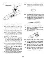
1.
Insert the soft rubber grommets into the mount-
ing holes of your servos.
2.
Measure from the bottom of your servo to the
underside of a grommet. Add about 1/8” to this
measurement to get the total distance between
the wing platform and the servo rail.
Referring to the plan, glue the rear rail against
Former “C”, at the predetermined height.
Place a servo on the rear rail and determine
the location of the front rail. Be sure to allow
enough clearance to allow easy insertion and
removal of both servos.
Glue the front servo rail in place.
3.
Place both the rudder servo and the elevator
servo in position on the servo rails. The eleva-
tor servo goes on the right (as viewed from the
pilot’s seat) and the rudder servo goes on the
left. There should be approximately 1/4”
between them.
Mark through the grommets for the location of
the servo mounting screws. Remove the ser-
vos.
Using a 1/16” drill bit, drill holes through the
rails for the screws.
4.
Referring to the plan, and using #2 x 3/8” sheet
metal screws, install the rudder servo on the
left and the elevator servo on the right.
Untape the pushrod wires and attach each of
them to the corresponding servo, as shown.
2.
Remove the servo wheel and install the CGM
pushrod connector, as shown. This device lets
you easily adjust the motor pushrod movement.
Remount the servo wheel with the pushrod con-
nector in the approximate position shown on the
fuse top view on the plan.
3.
From 1/16” scrap wire, cut a 2-1/8” length.
Make a 1/4” bend at the end. Roughen the
unbent end with sandpaper.
Slip the Snap-R-Keeper on the wire with the
clips toward the bend.
MOTOR SERVO INSTALLATION (3-CHANNEL)
1.
Referring to the plan for proper location, insert
the motor servo onto the fuse side with servo
mounting tape.
ELEVATOR AND RUDDER SERVO INSTALLATION
4.
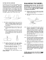
Position a CGM snap nut about 1” onto the
straight end of the wire.
Insert the wire through the pushrod connector
and add a second snap nut. (Trim the snap
nuts if they rub against the servo wheel.)
5.
Attach the bent end of the wire to the motor
switch bracket and secure by sliding the Snap
R Keeper clips over the bend.
Move the pushrod back and forth to simulate
servo action. Feel the OFF and ON switch lim-
its. Later, when setting controls, be sure to
adjust the snap nuts within the range of switch
movement.
INVERTED FUSE
33


