Chapter 4
4-18
5) Wait until "REPLACE MODE" is displayed.
6) Select "E/C REPLACE", and then press the [OK] button.
7) Check that "Turn Power Off!!" is displayed, and then turn off the power.
8) Turn on the power.
9) Check the firmware version. If it is not the latest version, update the firmware to the latest version.
4.3.13 Opening the Caps and Moving the Wiper Unit
0009-8793
The procedures for manually opening the caps and ink supply valves are presented below.
The carriage lock pin and caps need to be released manually if moving the carriage when the power is turned off. For details on the sensors and flags, refer
to TECHNICAL REFERENCE > Detection Functions Based on Sensors.
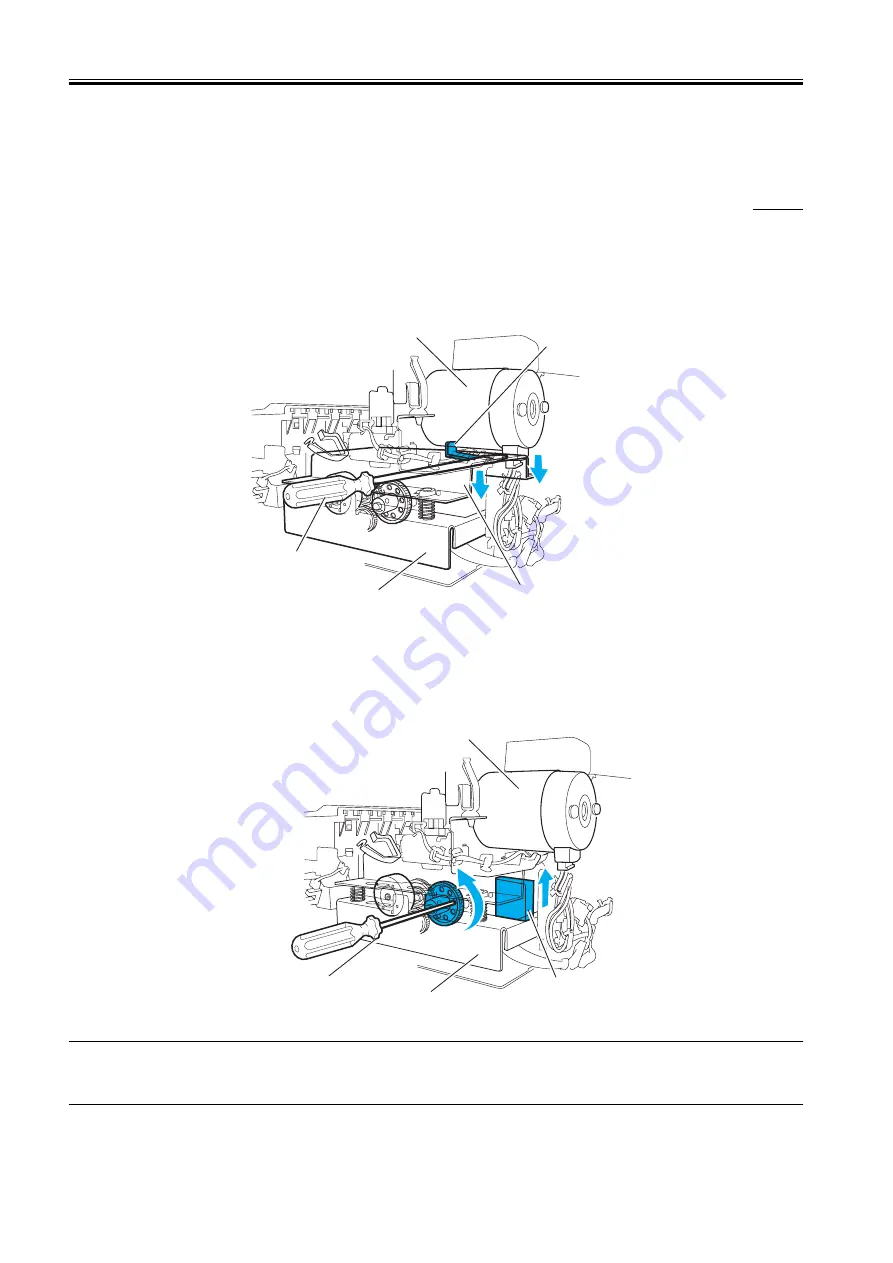
1. Opening the caps and releasing the carriage lock pins
1) Remove the right side cover, right rear cover, and right upper cover.
2) From the right side, insert a long driver on top of the upper side plate of the purge unit and push the long driver down while keeping it horizontal. This
lowers the cap and lock pin and allows the carriage to move.
F-4-36
2. Retracting the cap
If the purge unit cannot be removed because it is caught by the lower side of the cap extending from the bottom of the purge unit, rotate the purge gear of
the purge unit as follows and retract the cap.
1) Remove the right side cover, right rear cover and right upper cover.
2) Insert a long Phillips-head screwdriver into the hole in the purge gear from the printer right side.
3) Rotate the purge gear in the counter-clockwise direction.
F-4-37
MEMO:
After opening the caps and removing the carriage lock pin, rotating the gear further will close the caps after the wiper unit has completed the return
movement, and the carriage lock pin will rise and lock the carriage.
Carriage lock pin
Carriage motor
Purge unit
Long driver
Upper side plate
of the purge unit
Long Phillips-head screw driver
Cap
Carriage motor
Purge unit
Содержание W6400 Series
Страница 1: ...Apr 5 2005 Service Manual W6400 Series W6400 ...
Страница 2: ......
Страница 6: ......
Страница 12: ...Contents ...
Страница 13: ...Chapter 1 PRODUCT DESCRIPTION ...
Страница 14: ......
Страница 16: ......
Страница 40: ......
Страница 41: ...Chapter 2 TECHNICAL REFERENCE ...
Страница 42: ......
Страница 79: ...Chapter 3 INSTALLATION ...
Страница 80: ......
Страница 82: ......
Страница 86: ......
Страница 87: ...Chapter 4 DISASSEMBLY REASSEMBLY ...
Страница 88: ......
Страница 90: ......
Страница 115: ...Chapter 5 MAINTENANCE ...
Страница 116: ......
Страница 118: ......
Страница 122: ......
Страница 123: ...Chapter 6 TROUBLESHOOTING ...
Страница 124: ......
Страница 165: ...Chapter 6 6 39 F 6 7 Cover switch tool Cover switch tool ...
Страница 166: ......
Страница 167: ...Chapter 7 SERVICE MODE ...
Страница 168: ......
Страница 170: ......
Страница 185: ...Chapter 8 ERROR CODE ...
Страница 186: ......
Страница 188: ......
Страница 194: ......
Страница 195: ...Apr 5 2005 ...
Страница 196: ......


