Saddle Stitcher Unit
Outline
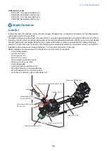
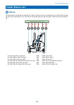
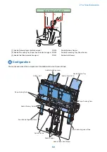
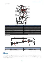
The saddle stitcher unit stitches and folds paper according to the instructions from the saddle stitcher controller PCB and delivers
the paper to the saddle delivery tray. Three sensors are provided along the paper feed path to detect the paper feed state and
jam.
[5]
[1]
[2]
[3]
[4]
[6]
Saddle Stitcher Controller PCB
M206
M205
M203
M207
M204
M201
[1] Saddle Gripper Motor drive signal
M205
Saddle Gripper Motor
[2] Saddle Alignment Motor drive signal
M203
Saddle Alignment Motor
[3] Saddle Delivery Motor drive signal
M207
Saddle Delivery Motor
[4] Saddle Paper Pushing Plate/Folding Motor drive signal
M204
Saddle Paper Pushing Plate/Folding Motor
[5] Saddle Feed/Paddle Motor drive signal
M201
Saddle Feed/Paddle Motor
[6] Saddle Paper End Stopper Motor drive signal
M206
Saddle Paper End Stopper Motor
2. Technical Explanation
59
Содержание Staple Finisher-AA1
Страница 1: ...Revision 4 0 Staple Finisher AA1 Booklet Finisher AA1 Service Manual ...
Страница 12: ...Product Overview 1 Features 5 Specifications 6 Names of Parts 14 Optional Configuration 20 ...
Страница 83: ...Periodical Service 3 Periodic Servicing Tasks 76 ...
Страница 87: ...3 Remove the 2 Connectors 1 2x 1 4 Parts Replacement and Cleaning 79 ...
Страница 89: ...Main Units Parts 4 5 6 7 8 1 2 3 4 Parts Replacement and Cleaning 81 ...
Страница 128: ...4x 1 2 2 3 3 2x 4 Parts Replacement and Cleaning 120 ...
Страница 150: ...Adjustment 5 Overview 143 Basic Adjustment 148 Adjustments When Replacing Parts 173 Other 184 ...
Страница 178: ...A B Feed Direction Stapling Position Fixing Screw A B Stitcher Unit Fixing Screw Fixing Screw Mark 5 Adjustment 170 ...
Страница 184: ... Adjsting Phase Angle of the Paddle Unit 1 Put off the belt 1 1 2 Lower the swing roller till its end 5 Adjustment 176 ...
Страница 193: ...Troubleshooting 6 Making Initial Checks 186 Processing Tray Area 187 Saddle Stitcher Area 188 ...
Страница 204: ...4 5 6 7 8 9 7 Installation 196 ...
Страница 205: ...10 7 Installation 197 ...
Страница 210: ...11 NOTE Keep the parts as illustration above Installation of Buffer Pass Unit 1 7 Installation 202 ...
Страница 223: ...2 3 2x 7 Installation 215 ...
Страница 224: ...APPENDICES Service Tools 217 General Circuit Diagram 218 ...

