Chapter 5
5-13
F-5-51
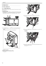
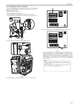
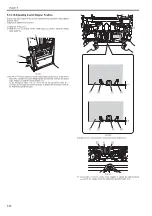
In the case of L-configuration size:
F-5-52
7) Pressing switch SW383 [1] or SW384 [2] determines adjustment level.
By pressing SW383 once, the LED [3] indicates "-1" and the stapling
position at the rear shifts to the rear . In the same way, by pressing SW384
once, the LED [3] indicates "+1" and the stapling position at the rear
shifts to the front.
- Adjustment range: +20 to -20 (shifting amount per unit: 0.5mm)
F-5-53
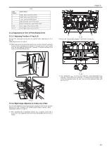
8) Press switch SW385 [1] to move the stapler to the rear.
F-5-54
9) Place A4 paper [1] on the intermediate process tray. (Be sure to push in
the paper to the rear side of the process tray)
Then, press switch SW383 to execute stapling.
F-5-55
10) Check that the stapling position is within the specified range [1] of 5 +/-
2mm using this result. If the stapling position is out of the specification,
go through the procedure again from step 6).
F-5-56
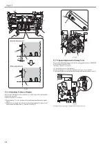
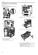
5.3.2.8 Adjusting Staple Position (1-stapling at the front)
0021-1714
Execute this adjustment in the case of displacement of stapling position (1-
stapling at the front) or replacing EEPROM on the finisher controller PCB.
Adjusting method is as follows:
1) Turn ON the power of the finisher.
2) Turn ON the power switch of the host machine to be on standby.
3) Open the front cover and put the door switch tool into the door switch [1].
SW382
SW381
SW383
(-)
(+)
ENTER
SW384 SW385
DSP381
[1]
SW382
SW381
SW383
(-)
(+)
ENTER
SW384 SW385
DSP381
[1]
SW382
SW381
SW383
(-)
(+)
ENTER
SW384 SW385
DSP381
[2]
[1]
[3]
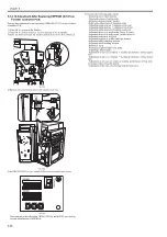
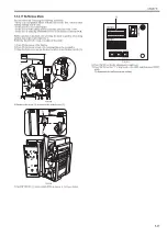
CAUTION:
If the LED indicates anything other than "0" meaning the adjustment failure,
execute the adjustment again.
SW382
SW381
SW383
(-)
(+)
ENTER
SW384 SW385
DSP381
[1]
[1]
[1]
Содержание Saddle Finisher-AF2
Страница 1: ...SERVICE MANUAL Saddle Finisher AF2 MARCH 6 2009...
Страница 2: ......
Страница 6: ......
Страница 12: ...Contents...
Страница 13: ...Chapter 1 Specifications...
Страница 14: ......
Страница 16: ......
Страница 22: ......
Страница 23: ...Chapter 2 Installation...
Страница 24: ......
Страница 26: ......
Страница 55: ...Chapter 3 Functions...
Страница 56: ......
Страница 58: ......
Страница 104: ...Chapter 3 3 46...
Страница 105: ...Chapter 4 Parts Replacement Procedure...
Страница 106: ......
Страница 110: ......
Страница 157: ...Chapter 4 4 47 F 4 213 3 2 1...
Страница 158: ......
Страница 159: ...Chapter 5 Maintenance...
Страница 160: ......
Страница 209: ...Chapter 5 5 47 F 5 221 SW382 SW381 SW383 ENTER SW384 SW385 DSP381 1...
Страница 217: ...Chapter 5 5 55 3 Door switch tool Front door switch ON tool number FY9 8006 No Name Description Composition Remarks...
Страница 218: ......
Страница 219: ...Appendix...
Страница 220: ......
Страница 221: ...General Timing Chart General Circuit Diagram Finisher Sorter DeliveryTray Saddle Finisher AF2...
Страница 222: ......
Страница 224: ......
Страница 225: ...Contents 1 General Circuit Diagram 1 Signal Names 1 General Circuit Diagram 9...
Страница 226: ......
Страница 243: ......
Страница 244: ......

