III. POWER SUPPLIES
A. Outline
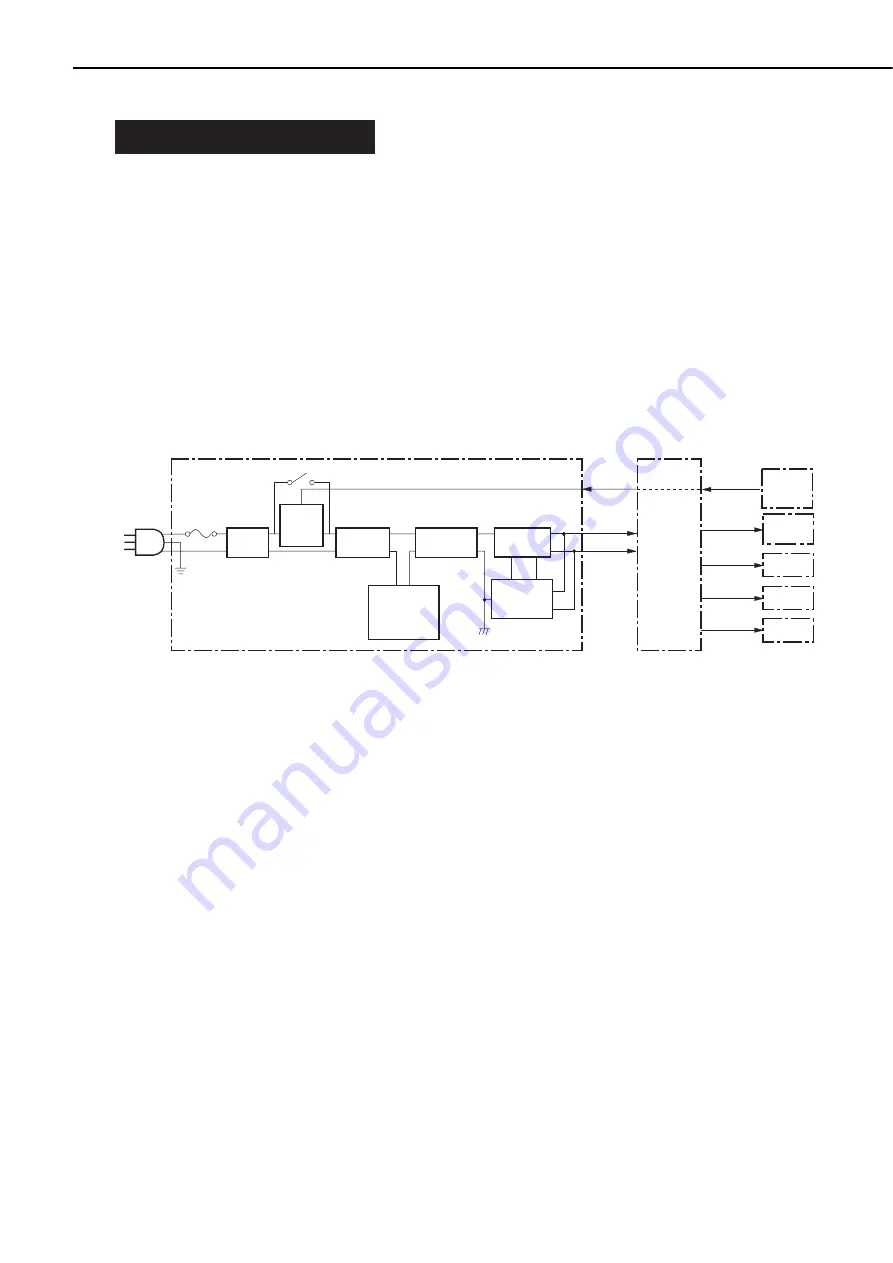
The power supply unit uses a remote switch.
When the printer power switch is turned ON, the printer outputs a command to the option
controller through the video controller. The option controller outputs a POWER ON signal
(PWRON-IN) to the power supply unit through the paper deck driver according to the
command. When the PWRON-IN signal is “H”, the power supply unit pr24 V and +5 V
to the paper deck driver.
+24 V is used to drive the lifter motor, feed motor, pick-up motor, clutches and solenoids,
and +5 V is used for sensors and ICs on the paper deck driver PCB.
The power supply unit uses the stand alone mode switch (SW1). This allows the paper deck
to be ON while the printer is OFF.
A block diagram of the power supply unit is shown below.
Figure 2-3-1
B. Protective Function
The +24V and +5V power supply circuits have the overcurrent protection function and the
overvoltage protection function that interrupt the output voltage automatically to prevent
failure of the power supply circuits if a trouble, such as a short, occurs in the load and results
in overcurrent flow or occurance of abnormal voltage.
Therefore, if the overcurrent or overvoltage protection function is activated and the DC
voltage is not output from the power supply circuit, turn the printer OFF, correct the trouble in
the load, and turn the printer ON again.
2 - 11
CHAPTER 2
+24V
PWRON-IN
+5V
+24V
+24V
+24V
+5V
PWRON-IN
Power supply
Noise
filter
Paper dec
k
driver PCB
Option
controller
PCB
Switchs
/sensors
Solenoids
Clutchs
Motors
Overvoltage
protection
curcuit
Smoothing
circuit
Transformer
Smoothing
circuit
Control IC
Overcurrent
protection
curcuit
Fuse
Remote
contorol
circuit
SW1
Содержание PD-82
Страница 8: ......
Страница 14: ......
Страница 16: ......
Страница 28: ......
Страница 30: ......
Страница 34: ...5 Rear cover 1 Remove the 4 screws and then the rear cover Screws Rear cover Figure 3 2 6 3 4 CHAPTER 3 ...
Страница 37: ...IV MAIN PARTS A Locations Lifter Figure 3 4 1 3 7 CHAPTER 3 ...
Страница 48: ...VII SOLENOID CLUTCH A Locations Pick up solenoid Registration clutch Figure 3 7 1 3 18 CHAPTER 3 ...
Страница 50: ...VIII MOTORS A Locations Lifter motor Pick up motor Feed motor Figure 3 8 1 3 20 CHAPTER 3 ...
Страница 58: ......
Страница 62: ...Figure 4 1 2 1 Pick up roller 2 Feed roller 3 Separation roller 4 4 CHAPTER 4 ...
Страница 80: ......
Страница 81: ...APPENDIX I GENERAL CIRCUIT DIAGRAM A 1 II LIST OF SIGNALS A 3 ...
Страница 82: ......
Страница 84: ......
Страница 88: ...PRINTED IN JAPAN IMPRIME AU JAPON 0199AB0 70 CANON INC The printing paper contains 70 waste paper ...


