6–16
ARRANGEMENT AND FUNCTIONS OF THE ELECTRICAL PARTS
H. Variable Resistors (VR) and
Check Pins by PCB
Of the VRs and check pins used in the machine,
those needed in the field when servicing the ma-
chine are discussed herein.
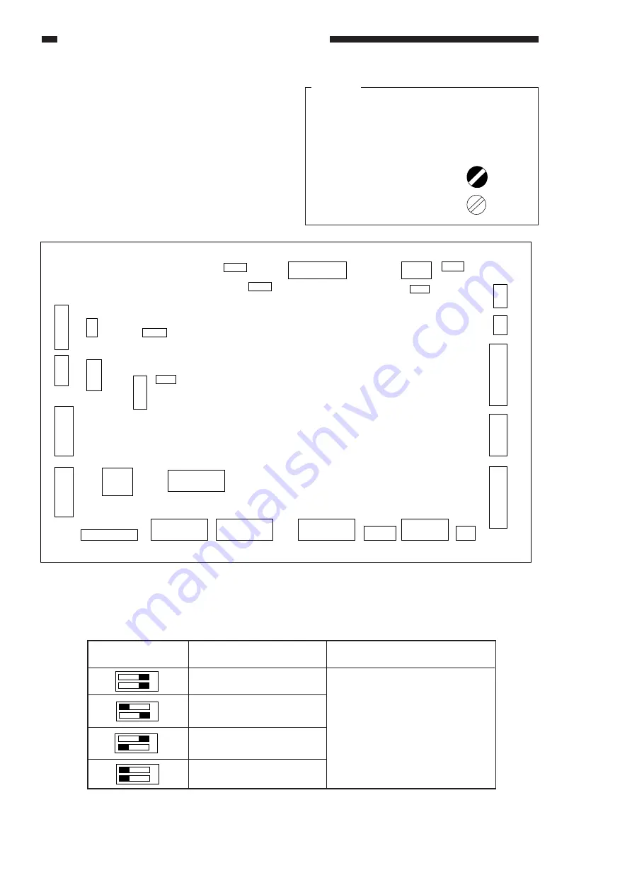
1. DC Controller PCB
Table 6-607
SW303
Description
SW303 settings determine how
the option counter (CNT2)
behaves.
Counter
Large size copy counter
Duplexing unit counter
Small size copy counter
No counter
Figure 6-608
1 2
ON
OFF
1 2
ON
OFF
1 2
ON
OFF
1 2
ON
OFF
6
J301
1
6
J304
1
1
J352
7
28
J305
15
11
4
J306
11
3
J314
1
14
20
J315
11
1
10
J316
1
15
1
J317
4
1
J319
5
1
J307
14
1
J302
5
5 J351 1
22
J308
12
1
11
J318
1
12
J309
1
15
24 J310
13
1
12
20 J312 11
1
10
J311
1
8
J313
1
4
J353
51
J322
1
4
J320
1
5
J325
3
1
J326
1
6
J321
4
1
J324
1
16
8
9
SW303
4
J303
1
Caution:
Do not touch VRs or check pins not mentioned
herein. They are for factory use only and require
special tools and instruments for highly precise
adjustment.
1.
VRs that may be used
in the field.
2.
VRs that must not be
used in the field.
Содержание NP6621
Страница 4: ...ii ...
Страница 8: ...vi ...
Страница 48: ...3 2 IMAGE FAULTS ...
Страница 49: ...3 3 IMAGE FAULTS NOT USED ...
Страница 50: ...3 4 IMAGE FAULTS B Image Fault Samples not available ...
Страница 80: ...4 16 TROUBLESHOOTING MALFUNCTIONS ...
Страница 98: ...6 8 ARRANGEMENT AND FUNCTIONS OF THE ELECTRICAL PARTS D PCBs Figure 6 603 1 2 3 4 5 6 7 8 9 10 11 12 ...
Страница 108: ...6 18 ARRANGEMENT AND FUNCTIONS OF THE ELECTRICAL PARTS 4 Fixing Heater Driver PCB Figure 6 611 J402 1 J401 W1 W2 ...
Страница 134: ...A 4 APPENDIX ...
Страница 135: ...A 5 APPENDIX C GENERAL CIRCUIT DIAGRAM not available ...
Страница 136: ...A 6 APPENDIX ...
Страница 144: ...A 14 APPENDIX ...


