


CHAPTER 4 SERVICE MODE
4-4
C.
Adjustment Mode (30)
1) Press the +/- key to select an item, and press the Copy Start key.
• The existing setting of the item will flash.
2) Press the +/- key to change the settings.
3) Press the AE key to store the new setting.
• The setting will stop flashing and remain on.
• A press on the Copy Start key will start copying operation.
4) As necessary, press the Clear/Stop key to return to item selection.
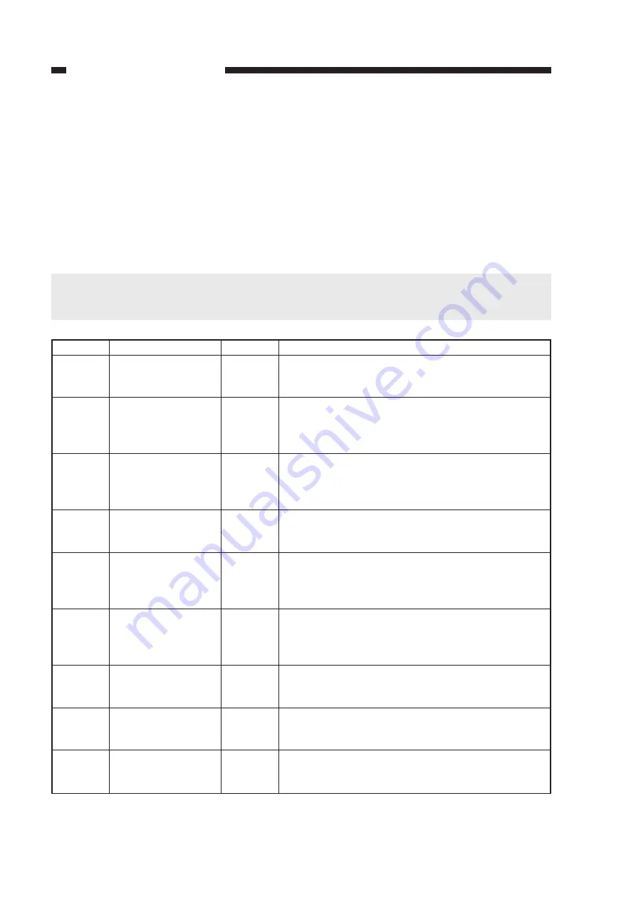
Notation
30
31
32
33
34
35
36
37
38
Item
Leading edge
margin adjustment
(REGIST)
Leading edge
non-image width
adjustment
(LE_BLANK)
Primary charging
output voltage
correction
(PRIMARY)
APVC measurement
current correction
(IP_OFST)
APVC measurement
voltage correction
(PW_OFST)
APVC measurement
current correction
(IP_ADJ)
Ratio fine
adjustment
(LENS_ADJ)
Pre-exposure lamp
output adjustment
(PREX_LP)
Lamp intensity
adjustment
(LAMP_ADJ)
Settings
0-99
0-99
0-30
0-99
0-30
0-30
0-30
0-99
0-99
Description
A higher setting will delay the copy paper in relation
to the image, reducing the margin.
Unit: 0.24 mm
A higher setting will increase the leading edge
non-image width.
Unit: 0.24 mm
Use it to correct the output voltage determined by
APVC.
(If you have replaced the drum unit, be sure to enter
the value recorded on the label.)
Correct the current value for APVC measurement.
(If you have replaced the drum unit, be sure to enter
the value recorded on the label.)
Use it to correct the level of voltage applied during
APVC measurement.
(If you have replaced the composite power supply
PCB, enter the value recorded on the PCB.)
Use it to correct the level of current measured during
APVC measurement.
(If you have replaced the composite power supply
PCB, enter the value recorded on the PCB.)
Use it to correct the lens position.
(Do not use it in the field.)
Use it to adjust the intensity of the pre-exposure lamp.
(If you have replaced the pre-exposure lamp, enter the
value recorded on the label attached to the lamp PCB.)
Use it to adjust the intensity of the scanning lamp.
Unit: 0.15 V (approx.; 120 V)
0.30 V (approx.; 220/240 V)
Caution:
If you have changed the setting of '34' or '37', be sure to execute 'U7' in user mode
(installation/drum replacement mode).
Table 4-2
Содержание NP6412
Страница 6: ......
Страница 12: ......
Страница 34: ......
Страница 46: ......
Страница 48: ......
Страница 92: ......
Страница 144: ......
Страница 176: ......
Страница 178: ......
Страница 192: ......
Страница 194: ......
Страница 220: ......
Страница 222: ......
Страница 256: ......
Страница 258: ......
Страница 282: ......
Страница 284: ......
Страница 286: ......
Страница 384: ......
Страница 388: ......
Страница 402: ...A 18 COPYRIGHT 1999 CANON INC CANON NP6512 6612 7120 7130 7130F REV 0 AUG 1999 PRINTED IN JAPAN IMPRIME AU JAPON ...
Страница 412: ...A 28 COPYRIGHT 1999 CANON INC CANON NP6512 6612 7120 7130 7130F REV 0 AUG 1999 PRINTED IN JAPAN IMPRIME AU JAPON ...
Страница 414: ......
Страница 424: ......
Страница 426: ...0899AB1 51 1 PRINTED IN JAPAN IMPRIME AU JAPON This pubication is printed on 70 reprocessed paper ...
Страница 430: ......
Страница 432: ......
Страница 434: ......
Страница 446: ...CHAPTER 2 STANDARDS AND ADJUSTMENTS 2 10 7 Remove the four screws 7 and detach the lens cover 8 Figure 2 15 7 7 8 ...
Страница 456: ...CHAPTER 2 STANDARDS AND ADJUSTMENTS 2 20 9 Detach the pulley clip 16 from the cable drive pulley 1 Figure 2 33 1 16 ...
Страница 484: ......
Страница 492: ......
Страница 502: ......
Страница 506: ......
Страница 516: ......
Страница 518: ...0899AB1 11 1 PRINTED IN JAPAN IMPRIME AU JAPON This pubication is printed on 70 reprocessed paper ...
Страница 599: ...PRINTED IN JAPAN IMPRIME AU JAPON ...


