background image

Содержание NP6012F

Страница 1: ...SERVICE MANUAL REVWON 1 SEPT 1995 Canon FY8 13DW010 COPtiGHT 1995 CANON INC CANOh NP6012 NP6012F NP60212 REV 1 SEPT 1995 PRINTED IN JAPAN ...

Страница 2: ......

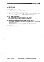
Страница 3: ...ines Uses a SURF fixing assembly l The use of the SURF fixing mechanism enables a 0 set wait time l In addition the maximum power consumption is 0 98 kW or less Cassette accommodating various types of paper and 2 way pick up l The universal cassette about 250 sheets accommodates paper of sizes between AULTR and A5lSTMT l In addition sheets as large as AWLTR to business card may be used manual Sepa...

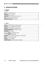
Страница 4: ...r 1 Type dy Desktop I Ge uir Fixed Lightsowcf Fluorescent lamp 17W l en Fixedlensarray Phutow lvf9m dbm OPC 24dia 2 System l 2 COPYRIGHT 0 1995 CANONINC CANON NP6012 NP6012F NP6212 REV 1 SEPT 1995 PRlNTEDINJAPAN IMPRIM AUJAPON ...

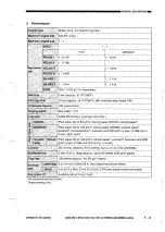
Страница 5: ...r Elan qe k il ddge 2 Ok1 5 mm 0 08kO O6 in two sided overlay one sided MI LefRighf 0 0 2 0 0 0 A4 0 0 4 0 0 0 LGULTR two sided overlay one sided Aitk f3ower oii Available about 5 min fixed As recommended bv Canon Single feeding only _ COPYRIGHT 0 1995 CANON INC CANON NP60121NP6012FiNP62i2 REV 1 SEPT 1995 PRINTEDIN JAPAN IMPRIMi AU JAPON l 3 ...

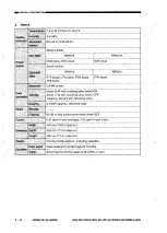
Страница 6: ...5 min reference only cwhi 0 4 kWh approx reference only N e ti m y ___ capyh g 66 dB or less sound power level under ISO OXme 0 01 ppm or less average 6 02 ppm or less max 478 mm I 8 8 in approx 453 mm D7 8 in approx 290 mm 01 4 in approx 20 0 kg 44 0lb approx including cassette Copy paper Keep wrapped to protect against humidity T r r Avoid direct sunshine keep at 4O C 85 or less l 4 MPYRIGHT 0 1...

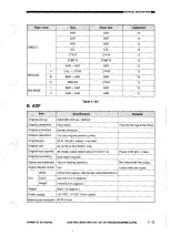
Страница 7: ...DIRECT Table l 101 B ADF COPVAlGtil Q 1995 CANONINC CANONNP6012 NP6012F NP6212 REV 1 SEPT 1995 PAlNTEDINJAPAN IMPRIM AUJAPON l 5 ...

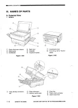
Страница 8: ...board glass Figure 1 301 0 Copyboard cover I Scanning lamp heater switch Figure l 302 Copy density correction dial l 6 COPYRIGHT 0 1995 CANONINC CANON NP60121NP6012FINP6212 REV 1 SEPT 1995 PRlNTEOINJAPAN IMPRIMiAUJAPON Static eliminator Delivety guide plate Figure l 303 Copy tray Power cord connector 8 Open close lever ...

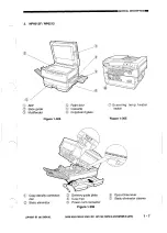
Страница 9: ...e l 304 Figure l 305 0 Scanning lamp heater switch 0 Copy density correction Delivery guide plate Open close lever Y dial Copy tray 0 Static eliminator cleaner II I Static eliminator Power cord connector Figure l 306 COPYRIGHT 0 1995 CANONINC CANONNP60121NP6012F NP6212 REV 1 SEPl 1995 PRlNTEDINJAPAN IMPAIM AUJAPON l 7 ...

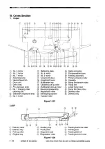
Страница 10: ...roller Developing cylinder Transfer roller Figure l 307 2 ADF Static eliminator Photosensitive drum Feeding assembly Primary charging roller Cassette Fixing film tension roller Fixing film Lower fixing roller Fixing film drive roller Delivery roller Delivery tray Delivery roller Delivery tray Pick up roller Original tray l 8 COPYRIGKT 1995 CANONINC CANON NP6012 NP6012F NP6212 REV 1 SEPT 1995 PRlNT...

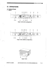
Страница 11: ...ONS A Control Panel 1 NP6012 Ad I 0 l 000 OB Figure l 401a Inch configuration 6 Figure l 401 b ABllnch configuration Figure 1 401 COPYRIGHT 8 1995 CANONINC CANON NP60121NP6012FINP6212 REY 1 SEPT 1995 PRlNTEDINJAPAN IMPRIMi AUJAPON 1 9 ...

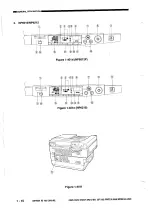
Страница 12: ...2 NP601ZNP6212 Figure 1 40ld NP6012F Figure l 401e NP6212 Figure l 40if l 10 COPWOHT 0 19 CANONINC CANONNp 012 Np6012F NP6212 REV 1 SEPT 1995 PAlNTEDINJAPAN IMPRIMiAUJAPON ...

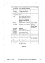
Страница 13: ...oner must be disposed of If the model does not have the function flashes when the waste toner must be 13 Jam indicator 14 Paper Select key Flashes when a jam occurs Selects the cassette as the source of paper or Selects the multifeeder Selects a default reproduction ratio Prevents delayed first copy time in a cold Table l 401 COPVRIGHI 0 1995 CANONINC CANONNPS012 NPS012F NP62i2 REV 1 SEPT 1995 PRl...

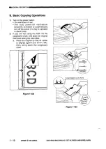
Страница 14: ...d in about 5 min 2 If you are not using the ADF lift the copyboard cover and place an original face down along the size index a Place the original so that its center is aligned against the arrow then bring down the copyboard cover Figure l 402 i Load paper up to here Figure l 403 l 12 COPYRIGHT 0 1995 CANONINC CANONNP60121NP6012F NP6212 REV 1 SEPT 1495 PRINTEOlNJAPANjIMPRIM AU JAPON ...

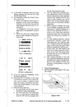
Страница 15: ...ch from automatic den sity adjustment mode to manual density adjustment mode between copying has started and the last copy is made however you cannot switch from manual density adjust ment mode to automatic density adjustment When copying is finished the Copy Count indicator indicates the initial copy count If copying stopped as a result of the absence of paper a press on the Copy Start key after ...

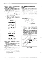
Страница 16: ... Count Zoom Set key then check the Copy Count indicator Press the Copy Start key l Be sure to remove each transparency delivered to the copy tray before the next one is delivered Figure l 406 1 14 COPYRIGHT 0 1995 CANONINC CANON NP6012 NP6012F NP6212 REV 1 SEPT 1995 PRlNTEDINJAPAN IMPRIM AUJAPON If the Transparency Is Not Picked Up Smootlily l Under certain environmental conditions transparencies ...

Страница 17: ...ake sure the paper is not moist Make sure that the paper is not curled Make sure that the paper is of 64 to 126 g m2 business card 200 g m or less In the case of a two sided copy each side may not be used more than once After the first copy run cool the paper sufficiently and remove the curl before feeding it for the second copy run COPYRIGHT 0 1995 CANONINC CANONNP6012 NP6012F NP6212 REV 1 SEPT 1...

Страница 18: ...ction Only in model with dr unit replacement timf automatic indication u3 Drum unit replacement indicator off mode Turns off the flashing Replace Drum Unit indicator U6 ADF cleaning mode Clean the ADF s original feeding path u7 Installation drum unit replacement mode Used to enter data Only in model withou necessary when installing drum unit replacemel the machine or replacing time automatic indic...

Страница 19: ... Charging Roller Cleaning Mode Ul Operate so that Ul appears on the count ratio indicator then press the Copy Start key l Ui starts to flash to indicate the exe cution of cleaning cleaning takes about 3 sec l Ul stops flashing and remains on when cleaning is finished Figure l 409 2 To end user mode press the AE key l The AE key remains disabled while user mode is being executed COPYRIGHT 0 1995 CA...

Страница 20: ...r mode press the Copy Start key and then the AE key l The AE key remains disabled while a copy count is being indicated 7 5 Drum Unit Replacement Off Mode U3 Only for a model with the drum unit replacement time automatic indication func tion 1 Operate so that U3 appears on the count ratio indicator then press the Copy Start key l U3 remains however the Replace Drum Unit indicator stops flashing an...

Страница 21: ...nit replacement time automatic indication func tion 1 Operate so that U7 appears on the count ratio indicator then press the Copy Start key l The indication changes to 71 2 Using the I key enter the value of PRIMARY recorded on the drum unit l Appears in the top left of the count ratio indicator while a value is being entered Figure 1 414 3 After entering the value of PRIMRY press the Copy Start k...

Страница 22: ... execute drum sensitivity automatic adjustment and toner stirring l The main motor will rotate and drum sensitivity automatic adjustment and toner stirring will start l After the execution the copier ends user mode automatically and stops operation in about 1 min l A press on the AE key while the above execution is taking place ends user mode however the AE key will not be accepted while a setting...

Страница 23: ... close lever to open the body Figure 1 419 4 Pull out any jam from inside the machine with care When the Copy Start key is pressed without paper on the multifeeder Check if paper is set in the cassette If the cassette is out of paper set copy paper If there is paper in the cassette go through the following 0 Open the right door and check if there is a jam Remove it if any Take out the stack of pap...

Страница 24: ...open close lever to open the body 3 Hold the toner cartridge level and shake Y it left and right several times Figure 1 421 2 Turn the toner cartridge clockwise until it stops and pull out the cartridge Figure l 423 4 Insert the toner cartridge carefully until it stops Figure l 424 Figure l 422 l 22 COPYRIGHT 0 1995 CANONINC CANON NP60i2 NWOlZF NP6212 REV 1 SEPT 1995 PAlNTEDINJAPAN lMPRIM AUJAPON ...

Страница 25: ...n Dial If the copy density is too high i e the image is too dark in density adjustment mode AE or manual you may adjust the copy density using the Density Correction dial 1 Shift up the open close lever to open the body 2 Adjust the position of the density correc tion dial Figure l 427 ACaution Do NOT throw the toner cartridge into fire it can burst or explode COPYRIGHT 0 1995 CANONINC CANON NP601...

Страница 26: ...ds to jam frequently advise the user to clean the following parts I I 1 If Images are Soiled a Copyboard Glass Copyboard Cover Wipe it with a moist cloth then dry wipe it If the dirt cannot be removed wipe it with a cloth moistened with mild detergent solu tion and dry wipe it b 1 2 3 Cassette Pick Up Roller Remove the cassette Open the right cover Keep the separation pad down wipe the cassette pi...

Страница 27: ...pad Multi pick up roller Copy paper Figure l 430 d 1 e 1 2 Feeding Belt NP6012F NP6212 only I Wipe the feeding belt while moving It rn the direction of the arrow with a cloth moistened with water be sure to wring the cloth well Figure 1 431 Separation Pad NP6012F NP6212 only Remove the ADF from the copier See IX of CHAPTER 4 for the steps to fol low Detach the separation pad cover using a coin or ...

Страница 28: ...NC CANON NP6012lNP6012FINP6212 AEV l SEPT 1995 PRlNTEOINJAPAN IMPRIM AUJAPON f Pick Up Roller You must clean the pick up roller when ever vou have reolaced the seoaration Dad 1 2 demove the separation pad unit Wipe the pick up roller while moving it in pick up direction with a cloth moistened with alcohol or water be sure to wring the cloth well before bringing it into con tact with the roller Pic...

Страница 29: ... open the body Clean the static eliminator with the static eliminator cleaner 0 Brush out any dirt paper lint for example from the groove in the static eliminator Figure l 439 4 Close the body as soon as you have fin ished cleaning Figure l 438 NP6012F NP6212 COPYRIGHT 0 1995 CANONINC CANONNP60121NP6012F NP6212 REV 1 SEPT 1995 PRlNTEDINJAPAN IMPRIM AUIIAPON l 27 ...

Страница 30: ...posi tion Drum unit lever Figure l 440 2 The toner cartridge has been turned and positioned as specified 3 The fixing lever is at the LOCK position Fixing lever Figure l 442 Unless the above three points are satis fied the lock mechanism will activate pre venting the top unit from closing Figure 1 441 l 28 COPYRIGHT 8 1995 CANONINC CANON NP6012 NP6012f NP6212 REV 1 SEPT 1995 PRlNTEOINJAPAN IMPRIMi...

Страница 31: ...opyboard glass W Transfercharging roller Static eliminator Lower fixing roller Figure 2 101 Latent static Image Formation I _ _________ _ 4 Development Flow of copy paper Casselteimanual feed t _ Rotation of photosensitive drum Figure 2 102 COPYRIGHT Q 1995 CANON INC CANONNP6012 NP60i2FINP6212 REV 1 SEPT 1995 PRlNlEDINJAPAN IMPRlMbAUJAPON 2 1 ...

Страница 32: ...103 B Static Latent Image Formation Block The static latent image formation block consists of tow steps primary charging and image exposure At the end of this block the areas on the photosensitive drum corre sponding to the black areas of the original are left with negative charges and those cor responding to the white areas of the original are rid of negative charges These images created by negat...

Страница 33: ...he surface of the photosensitive drum is charged to a uniform negative potential in preparation for the formation of static latent images The copier uses its primary charging roller to directly charge the photosensitive drum primary charging The primary charging roller is made of conducting rubber and a DC bias is applied to the roller Reference A direct charging system provides such advantages as...

Страница 34: ...ins The toner has insulating characteristics and becomes positively charged by the friction between the rotating cylinder and the blade The toner is moved between the rotating developing cylinder and a blade where it is charged to a positive potential and deposited on the developing cylinder in a thin uniform layer The developing cylinder receives both AC bias and DC bias negative component at the...

Страница 35: ...r toner from the sur face of the transfer drum to the copy paper The copier uses a roller transfer system which has the following advantages when compared with the conventional corona transfer system l Generates virtually no ozone l Provides good feeding since copy paper is retained by both the transfer charging roller and the photosensitive drum Reference Toner may collect on the transfer roller ...

Страница 36: ...er moves through the fixing film and the pressure roller The fixing film has a seamless construc tion and is made of special material so that melting toner will not stick to the film fur ther the surface of the pressure roller is cleaned by a cleaning roller I Fixing step 7 Theryistor The fixing heater is a flat heater and heats only the area where the fixing film comes into contact this design el...

Страница 37: ...py run the cleaning blade scrapes off the residual toner from the photosensitive drum by way of cleaning the photosensitive drum surface The scoop up sheet then is used to collect such toner i COPYRIGHT 0 1995 CANON INC CANON NP5412lNP6012FINP6212 REV 1 SEPI 1995 PRINTED INJAPAN IMPRIMt AU JAPON 2 7 ...

Страница 38: ...xposure In nip exposure part of the light from the pre exposure lamp is directed to the area where the photosensitive drum is in contact with the primary charging roller thereby ensuring the stability of primary charging Preexposure lamp Primary charging roller _ path of light nip exposure path of light pre exposure Figure 2 115 2 8 COPYRlGtlT819 CANONINC CANON NP6012 NP6012F NP6212 REV 1 SEPT 199...

Страница 39: ...ivided into four functional blocks namely pick up feeding exposure image formation and control I I Control panel f Control circuitry Exposure block Optical path _ Figure 3 101 COPYRIGHT 0 1995 CANONINC CANONNP6012lNP6012FINPS212 REV 1 SEPT 1995 PAlNTEOINJAPAN IMPRIMiAUJAPON 3 1 ...

Страница 40: ...ery paper detection Film displacement detection Waste toner detection Cassette detection model with drum unit replacement time automatic indicator function only IQIOI I I CPU1 5 24V t i j 1 Primary charging roller Developing cylinder Transfer charging I roller f Static eliminator Pick up solenoid Registration clutch solenoid jyi solenoid Scanner lens drive switching Cassette multifeeder pick up sw...

Страница 41: ... home position 1 when light blocking plate is at PSZ 1 when PS3 detects paper 1 when light blocking plate is at PS3 0 when PS4 detects fixing film 0 when light blocking plate is at PS4 0 TNFULL when toner reaches specific level 1 2 when light blocking plate is at PS5 0 2 5v RPD when Q751 detects paper 1 when light blocking plate is at Q751 0 DIG2 CPD 2 THI X TH2 I when paper is present in cassette...

Страница 42: ...1995 CANONINC Q4V _t 4EREF 4E LEXP ns 3lG1 iEAT IGI z tT iEAT rNMONl when reflected light increases voltage lowers when light from fluorescent lamp increases voltage lowers Keys and LEDs are wired in a matrix on the control panel PCB the DC controller reads the key inputs and turns on or flashes the LEDs Combinations of 3 bit signals are used to correct the variations in the resistance of the fixi...

Страница 43: ...txocessor Primary charging roller Developing cylinder Transfer charging roller Static eliminator driver 1 11 I High voltage circuit 1 i a t24V Door switch Figure 3 105 dtITRD 1MD tLOC See p 3 7 r Fixing heater drive signal used to control the temperature of the fixing heater 1 Micro processor I Communication with composite power supply PC0 COPYAlGHl 0 1995CANON INC CANON NP6012 INP6012FINP6212 REV...

Страница 44: ...e lamp rear KII F61 sB Lp Side blank exposure lamp front Primary charging roller cleaning solenoid Transfer charging roller escape solenoid J121 1 PEXP Pre exposure lamp PCB 2 24V J119 1 TCNTD Total copy counter MCI 2 24V when O primary charging roller cleaning solenoid turns on when 0 transfer charging roller escape solenoid turns on when 0 pre exposure lamp turns on when O total counter turns on...

Страница 45: ...he drive circuit of the motor driver turns on thereby rotating the main motor Ml at a specific revolution While the main motor is rotating at a specific revolution the main motor driver PCB sends the speed state signal MLOCK O to the DC controller PCB If for some reason fluctuations occur in the rota tion of the main motor the MLOCK signal goes I If MLOCK l continues about 1 set while the main mot...

Страница 46: ...ey On 3 2 Set approx After Power On Power switch Copy Start key ON ON L ZZEl reverse I scanner home position detection II lens home position detection Figure 3 108 I 3 8 COPYRIGHT 0 19 CANON INC CANON NP 50121 NP6012FI NP6212 REV 1 SEPT 1995 PRINTED IN JAPAN IMPRIM AU JAPON ...

Страница 47: ...ly After Power On less than 3 2 set Z reverse I scanner home position detection II lens home position detection Figure 3 109 I Y COPYRIGHT 0 1995 CANONINC CANONNPMl2 NPS012F NP6212 REV 1 SEPT 1995 PRlNTEDINJAPAN IMPRIM AUJA ON 3 9 ...

Страница 48: ...the residual charges from the photo sensitive drum and stabilizes the sensitivity of the photo sensitive drum in preparatior for cpying operation l Pre heats the scanning lamp and makes preparations unti the drive intensity becomes stabilized The scanning lamp illuminates the original and the reflected optical image is projected on the photosensitive drum by way of mirrors and lenses The scanner i...

Страница 49: ...oving the No 4 and No 5 mirror units as shown in Figure 3 202 The scanner drive system changes the reproduction ratio around the drum by mov ing the No 1 mirror faster reduction or slower enlargement relative to the periph eral speed of the drum Reference 1 In DIRECT the speed at which the No 1 mirror is moved is the same as the peripheral speed of the drum 2 The length of the optical path is long...

Страница 50: ...opyboard glass N N N ENLARGE REDUCE Movement in 0 ENLARGE REDUCE 1 L No 45 mirror unit Figure 3 202 3 12 COPYRIGHT 0 1995 CANONINC CANONNPS012 NP6012F NP62i2 REV 1 SEPT 1995 PAlNTEOINJAPAN IMPRIM AUJAPON ...

Страница 51: ...rs and lens cable At the same time the No 4 5 mirror unit moves according to the travel reproduction ratio of the lens unit changing the length of the optical path At this time the side blank exposure lamp also moves in relation to the lens to perform black erasure at the front and the rear 0 4 5 mirror unit Lens travel detecting shaft for side blank exposure lamp DC controller PCB Figure 3 203 CO...

Страница 52: ... scanner is moved in reverse remains constant regardless of the select ed reproduction ratio about 3 4 times as fast as in forward in DIRECT The distance over which the scanner travels varies according to the length of copy paper and the selected reproduction ratio The scanner motor drives the lens drive system in addition to the scanner system Scanner home position sensor PSI Figure 3 204 Motor d...

Страница 53: ...croprocessor on the DC controller PCB controls the forward travel distance of the scanner with reference to the rising edge of the scanner home position signal The forward trav el distance varies depending on the length of copy paper and the selected reproduction ratio in ENLARGE if the ratio is less than 130 the scanner is moved forward for A4 297 mm if the ratio is 130 or more the scanner is mov...

Страница 54: ... frequency and the sequence of drive pulses SC A through SC B The motor drive voltage on off switching circuit supplies power to drive the motor and removes power to stop it The current switching circuit sets the current flowing to the motor according to the speed of rotation the motor driver circuit is used to control the copying modes and reproduction ratios from rated current according to the s...

Страница 55: ... measures the density of the original l controls side blank exposure Copyboard glass I P Scanning lamp I 1 I I Light adjustment sensor Developing cylinder 3 Preexposure lamp Primary charging roller Static Transfer eliminator roller Fluorescent lamp driver I I Q501 I High voltage circuit DC controller PCB I Microprocessor Composite power supplyPCB Figure 3 301 COPYRIGHT 0 1995 CANON INC CANON NP901...

Страница 56: ...ous Power switch ON Copy Start key ON ZZ reverse Figure 3 302 DIRECT 2 Copies Continuous Copy Start key pressed immediately after power on BZ2 reverse Figure 3 303 3 18 COPYRIGHT 0 1995 CANON INC CANON NP6012 NP6012F NP6212 REV 1 SEPT 1995 PRINTEDIN JAPAN IMPRIMi AU JAPON ...

Страница 57: ...ed to deter mine the intensity of the pre exposure lamp is stored in the CPU on the DC controller PCB The CPU on the DC controller PCB detects the voltage used to drive the pre exposure lamp and corrects the PWM refer ence value so that the pre exposure lamp may be driven at a specific intensity Reference You must enter the PWM reference value PREX_LP in service mode whenever you have replaced the...

Страница 58: ...reover its intensity does not stabilize for some time if its ambient temperature is low In consideration of these characteristics of the fluorescent lamp the copier is equipped with an intensity sensor so that the originals may be illuminated only after the intensity of the fluorescent lamp has stabi lized The copier does not start copying opera tion until the intensity of the fluorescent lamp has...

Страница 59: ...on control signal to the microprocessor QlOl on the DC controller PCB In response the microprocessor QlOl on the DC controller sends the pre heating control signal FLPRHT to the pre heating voltage control circuit to execute pre heating control suited to the duty ratio of the on control sig nal for pre heating control Reference Activation of the Fluorescent Lamp The fluorescent lamp repeats turnin...

Страница 60: ...oprocessor Q501 on the composite power supply PCB The intensity sensor checks the intensity of the scanning lamp and generates activa tion power to suit the intensity The micropro cessor on the other hand finds out the intensity of the scanning lamp based on the activation power to send the scanning lamp on signal FLON to the on control circuit b Intensity Lower Than the Specified Value The microp...

Страница 61: ...e DC bias voltage level l controls the scanning lamp ON voltage level The primary charging roller is given a DC bias so as to maintain the surface poten tial of the photosensitive drum to a specific value The DC bias is switched according to whether or not a copy image is being formed Reference DC component 9OO 1376V Microprocessor Composite power supplyPCE DC controller PCB Figure 3 307 COPYRIGHT...

Страница 62: ...ge is switched by the microprocessor on the composite power supply PCB by varying the DC bias control signal PDCPWM according to the DC bias switching timing signal sent by the micropro cessor on the DC controller PCB during copying 900 V other 1376 V b Controlling the DC Bias to a Specific Voltage The DC bias is controlled to a specific voltage by the microprocessor on the com posite power supply...

Страница 63: ...y charging roller bias application voltage level APVC control and the scanning lamp ON voltage level ALVC control thereby ensuring a spe cific light area potential VL and dark area potential VD at all times Study the following for an idea of how the mechanism is activated after power on during initial rotation for 1st copy Flow A specific voltage of about 1 376 kV is applied to the primary chargin...

Страница 64: ...voltage level of the DC bias according to the copy density set tings The developing cylinder is given AC and DC biases during copying operation While the photosensitive drum is rotat ing except during development about 500 V is applied to the developing cylinder regardless of the position of the density adjusting lever thereby preventing adhesion of excess toner to the surface of the photo sensiti...

Страница 65: ...out 3 5 set after the Copy Start key is pressed the microprocessor on the DC con troller PCB sends the developing AC bias on signal DVACON to the microprocessor on the composite power supply PCB The microprocessor on the composite power supply sends the AC bias oscillation signal ACBIAS to the amplifier which in turn drives the transformer T301 and gen erates an AC bias for the developing cylin de...

Страница 66: ...DC bias voltage there by correct ing foggy images caused by changes in the sensitivity of the photosensitive drum The density correction dial functions when the density is adjusted in manual mode or during automatic density adjustment mode Figure 3 310 See Figures 3 311 and 312 for changes in the DC bias according to the setting of the density adjusting lever in manual mode and to the changes in t...

Страница 67: ...of the main motor Ml transmitted by the drive gear The waste toner scraped by the clean ing blade is forwarded inside the drum unit by the toner feeding blade for collection The level of toner inside the developing assembly is monitored by the toner antenna T DC controller PCB Composite power supply PCB detection PCB Drum unit COPYRIGHT 1995 CANON INC 1 dleaning blade Toner antenna assembly Waste ...

Страница 68: ...etecting PCB receives an AC b as equal to the AC bias applied to the developing cylinder and an AC bias that represents the level of toner by the toner level antenna The AC bias applied to the developing cylinder is used as a reference signal and the AC bias from the toner level antenna is used as the toner level signal The toner level detection PCB compares these two types of signals and sends th...

Страница 69: ...e copy in the case of continuous copying it stops operation after making five copies after the absence of toner has been detected The ADD TONER indicator turns off when you turn off and then on the power switch after the indicator has come on 1 enabling copying operation However the indicator will flash once again after a single copying operation You can make as many as 100 copies while the ADD TO...

Страница 70: ... the copy count is stored when the power is turned dff and the new count is added to it when the power is returned l Condition 2 Copies made since power on are count b Operation When the cleaning solenoid SL5 turns on ed and icleaning is executed when the 20th the cleaning pad is butted against the copy hag been discharged The copy count primary charging roller to stat l cleaning is cleared when t...

Страница 71: ...eaning Operation Timing Chart Condition 1 Jower off m gqqq Figure 3 316 Condition 2 power off Figure 3 317 COPVRKiHT 1995 CANONINC CANONNP6012lNP6012FINP6212 REV 1 SEPT 1295 PRmTEDINJAPA IMPRlM AUJAPMI 3 33 ...

Страница 72: ...1 the toner feeding blade increases Further when torque is imposed on the toner feeding blade the coupling gear becomes disengaged cutting the drive to the toner feeding blade thereby causing the flag to move away from the waste toner sen sor PS5 When the flag leaves the waste toner sensor the Replace Drum Cartridge indicator a on the control panel starts to flash in the case of a model with the d...

Страница 73: ...o In addition if you install a drum unit which does not accommodate the function in a copier model which is designed for the function copying operation will be suspended while CC Change Cartridge is indicated on the count ratio indicator Control panel DC controller PCB COPYRIGHT Q 1995 CANONINC CANONNP6012lNP6012FINP6212 REV 1 SEPT 1995 PAINTEDINJAPAN IMPRIMi AUJAPON 3 35 b Operation l Drum Unit I...

Страница 74: ...trol panel and suspends copying operation while indicating CC on the count ratio indicator In continuous copying the operation is suspended after making all the copies To reset the copier when its operation has been suspended replace the drum unit with a new one 29 000 Flashing Indicates Yes Indicates that the drum l You may turn off the 30 000 1 30 100 ON count ratio unit must soon be indication ...

Страница 75: ...opier applies a positive voltage at a specific timing to return the toner from the transfer roller to the photosensitive drum l during initial rotation after the Copy Start key is pressed l while the scanner is moving in reverse l during last rotation c Reference Bias ATVC Changes in the environment or deterio ration of the transfer roller can change the resistance of the transfer roller ultimatel...

Страница 76: ...ias l controls the transfer bias to a constant voltage l corrects the voltage level of the transfer bias ATVC switches the polarity of the DC bias cleaning Photosensitive Transfer c drum charging roller Microprocessor Microprocessor DC control PCB Figure 3 321 3 38 COPYRIGHT 0 1995 CANONINC CANON NP60iZ NP6012F NP6212 REV 1 SEPT 1995 PRlNTEDINJAPAN IMPRIMtAUJAPON ...

Страница 77: ... transfer roller The current detection circuit on the composite power supply PCB sends measurements of the cur rent to the microprocessor in the form of the current detection signal The microprocessor determines the voltage to be applied to the transfer roller based on such data This control is executed once during ini tial rotation after a press on the Copy Start key OPERATIONSANDTIMINGI I b Afte...

Страница 78: ...The copier s AE mechanism does not execute an AE scan rather it measures the density pf the original during initial rotation at the scanner home position for this reason the copying speed remains the same in both AE and non AE modes Figure 3 322 shows the circuit that con trols the measurement of the density of origi nals AE sensor I Copyboard glass Amplifier circuit DC controller PCB developing D...

Страница 79: ...the AE signal four times and aver ages the measurements to compute the developing DC bias which best matches the averaged density of the original it then sends the developing DC bias signal and the developing DC bias on signal to the microprocessor on the composite power supply PCB The microprocessor on the composite power supply PCB generates the developing DC bias control signal DCBPWM based on ...

Страница 80: ...Screwdriver Figure 3 325 Stop shorting the jumper wires press the key so that 40 appears on the ratio count indicater than press the start key l The scanning lamp should turn on and the main motor Ml should rotate Turn VR103 on the DC controller PCB fully clockwise Figure 3 326 Place a newspaper on the copyboard and close the copyboard cover Turn VR102 so that the reading in the display is between...

Страница 81: ...ng but the print is dark enough l If fogging is noted or the characters are too light repeat the steps starting with step 1 once again l If the problem cannot be corrected after going through the steps once again use the density correction dial VR107 WI07 Figure 3 329 COPYRIGHT 0 1995 CANON INC CANON NPQQ12lNP6012FiNP62i2 REV 1 SEPT 1995 PRINTEO IN JAPAN IMPRIMP AU JAPON 3 43 ...

Страница 82: ... detecting shaft for reduced copies for blanking out the non image areas Rear side blank exposure lamp Lens travel detecting shaft Reflecting plate Front side blank exposure lamp Reflecting plate front Figure 3 330 A B B A Photosensitive drum L Non image area REDUCE i A position of the side blank exposure lamp at time of DIRECT ENLARGE B position of the side blank exposure lamp at time of REDUCE F...

Страница 83: ... I PS3 Delivery paper sensor multifeeder is controlled by the registration I 1 roller so that it matches the leading edge of Q751 Pre registration rollerpaper sensor the image on the photosensitive drum it is then moved to the transfer separation feed Table 3 401 ing and fixing assemblies before it is dis charged to the copy tray DC controller PCB gg Mul Photosensitive z d pick drum ii n Cassette ...

Страница 84: ...utch control ring and pick up solenoid SLl When the solenoid turns on the pawl moves away from the control ring thereby allowing the drive of the main motor Ml to be transmitted to the pick up roller When the pick up roller starts to rotate copy paper is picked up and sent as far as the registration roller The registration roller in turn serves to control the copy paper so that it matches the lead...

Страница 85: ... cam gear is designed to stop at a specific location When the solenoid SLl turns on while the mechanism is in this spatial relationship the pawl moves away from the control ring allowing the drive of the main motor Ml to be transmitted to the multifeeder pick up roller When the multifeeder pick up roller rotates copy paper is picked up and sent as far as the registration roller The registration ro...

Страница 86: ...rom the pre registra tion pap er sensor Q751 it turns on the reg istration solenoid at a specific timing When the registration solenoid turns on the paw1 moves away from the control ring allowing the drive of the main motor to be transmitted to the registration roller and moving the copy paper to the photosensitive drum Spring clutch aper detecting lever DC controller PCS roiier sensor Q751 Figure...

Страница 87: ... of service mode registration adjustment II Used for measuring the length of copy paper length of copy paper mm 92 mm s x II s 11 mm IO mm 92 mm s speed at which copy paper is moved 11 mm distance between pre registration sensor and registration roller IO mm length of actuator of the pre registration sensor Figure 3 406 COPYRIGHT 0 1945 CANONINC CANONNP60121NP6012FINP6212 REV 1 SEPT 1995 PRlNTEDIN...

Страница 88: ...he lower fixing HTRD to control the temperature of the fix roller ing heater The temperature of the fixing heater is monitored by the thermistor THl and is communicated to the microprocessor on the DC controller PCB as the fixing heater tem perature signal THl The rear end of the fixing heater is equipped with a sub thermistor TH2 to check for overheating Drive roller Delivery roller Lower fixing ...

Страница 89: ... c5v 4 Relay RLlOl r I 5v i Timer circuit end overheating error temperature N DC controller PC COPYRIGHT 0 1995 CANON INC CANON NPM121NP6012FINP6212 REV 1 SEPT 1995 PAlNlEDlN dAPAN IMPRIM AU JAPON 3 51 ...

Страница 90: ... mode The control temperature of the fixing heater is determined by any of the following three ways The copier keeps track of the number of copies made until the power is turned off or the auto shutoff mechanism about 5 min is activated during which time the effective control tem perature will not be changed 2 3 120 Corhigher bl y r atura b wrsr rjte on c y y r r Q tf mphture i i Lower than 100 C ...

Страница 91: ...OPERATIONSANDTIMINGI Ipj sincepower on 1 9 15 20 Figure 3 409 COPYRIGHT Q 1945 CANONINC CANONNP60121NP6012FfNP6212 REV 1 SEPT 1995 PRlNTEDINJAPAN PRIMt AUJAPOV 3 53 ...

Страница 92: ... to control the phase of the power supplied to the fixing heater HTRD c I Supply power I to the heater 1 i 1 7 1 4 Mrrecting the Variation in the Resistance of the Fixing Heater The plane shaped heater used as the fixing heater has production variations in its resistance that would hinder proper execu tion of thermal control of the fixing heater To correct possible problems the copier compensates ...

Страница 93: ...and a press on the Copy Start key then will make the remaining number of copies 6 Protection Mechanisms The copier is equipped with the following protection mechanisms to prevent malfunc tion of the fixing heater a Thermistor THl TH2 The microprocessor on the DC controller PCB monitors the voltage of the thermistor THl TH2 if it detects a high temperature error or a low temperature error it sends ...

Страница 94: ...the fixing film has become displaced toward the rear the copier moves up the front of the tensiofl roller The tension roller is designed to stop where the fixing film can move without dis placem ent by the work of the balance spring and the wire If the fixing film becomes displaced toward the rear or the front in excess of the range within which displacement is correct ed the fixing film displacem...

Страница 95: ...tation force of the friction roller increases or decreases in proportion to the area of the fixing film that comes in contact with the friction roller Friction roller I _ Balance spring Figure 3 413 Weaker I Rotation power of friction roller Smaller Larger Figure 3 414 Stronger Weaker Coverage of fixing film Smaller Larger Figure 3 415 When the fixing film becomes displaced toward the rear the are...

Страница 96: ...ion of the balance spring become balanced c Measures for E007 Use fixing film displacement correction mode if E007 is indicated as follows 1 Turn off the power switch and leave the copier alone for about 10 min l The temperature of the fixing heater will drop below 100 C 2 Turn on the power switch l The copier indicates C on the control panel and the fixing assembly becomes activated moving the fi...

Страница 97: ...microprocessor has the following five no paper jam detection sequences and it also identifies a jam if any of the sensor detects copy paper at power on 1 Absence of Paper in the Multifeeder Pick Up Assembly pick up delay jam In multifeeder mode if copy paper does not reach the registration sensor within a specific period of time the copier identifies a jam stops the main motor in about 3 set and i...

Страница 98: ...Copy Start key ON Figure 3 419 no papeij Copy Start key ON Figure 3 420 jam 3 60 COPYRIGHT Q 1995 CANONINC CANON NP6012 NP6012F NP6212 REY 1 SEPT 1495 PAlNTEDINJAPAN IMPRIMiAUJAPON ...

Страница 99: ...age Copy Start key y Pick upclutch solenoid SLI Jam check Pre registration roller paper sensor Q751 Main motor Figure 3 421 b Singlefeeder Pick Up Delay Jam If copy paper does not reach the registration sensor within a specific period of time after paper has been picked up the copier identifies a pick up delay jam stops copying operation and flashes the Jam message Figure 3 422 COPYRIGHT Q 1995 CA...

Страница 100: ...very sensor within a specific period of time because of a feeding problem the copier identifies a delivery delay jam stops copying operation and flashes the Jam message Figure 3 424 5 Delivery Stationary Jam If copy paper does not reach the delivery sensor within a specific period of time because of a feeding problem the copier identifies a delivery stationary jam stops copying operation and flash...

Страница 101: ...h serves to discharge ozone and cool the inside of the machine The fan is driven directly by the main motor Ml by means of a belt Figure 3 501 COPYRIGHT 0 1995 CANONINC CANON NPS012fNP6012FINP 212 REV 1 SEPT 1995 PRlNTEDINJAPAN IMPRINI A JJAP JN 3 63 ...

Страница 102: ...e circuit Scanning lamp LIE control circuit rer uit j Figure 3 601 DC controller Fixing heater Scanninglamp heater Scanning lamp Primarychargingroller Developing roller Transfer roller Static eliminator 3 64 COPYRIGHT 0 1995CANON INC CANON NP6012 NP60i2FINP6212 REV 1 SEPT 1995PRINTED INJAPAN IMPNIt AUJAPDN ...

Страница 103: ...ut to back up data on error codes EOOO EOOl E002 E003 the copier uses a litium battery BATI located within the DC controller cir cuit using the battery the appropriate error information will be indicated on the control panel when the power is returned informing the presence of an error associated with the fixing heater Acaution Replace the lithium battery only with the one listed in the Parts Cata...

Страница 104: ...panel Dl I Clzontroller PCI I t f B Relay RLIOl ti t5v f Main trans former T102 Power supply DC power SUPPlY Figure 3 602 5v t24VR 24VU I 3 66 COPYRIGHT 0 1995 CANONINC CANONNP6012 NP6012F NP6212 REV 1 SEPT 1995 PRlNTEDINJAPAN IMPRIM AUJAPON ...

Страница 105: ...DC bias l transfer bias 3 Error in the Control Value low volt age If the composite power supply PCB finds that the difference between the setting for 24 V of the DC output and the control value is not as specified it will indicate E603 on the display of the control panel 4 Error in the Communication with the DC Controller If the DC controller PCB finds an error in the communication between the DC ...

Страница 106: ...ay starting with the topmost original moves them through the copyboard and delivers them See Figure 3 701 for an outline of the feeding route Or ginql tray Figure 3 701 3 68 COPYRIGHT 0 19 CANON INC CANON NP6012 NP6012F NP6212 REV 1 SEPT 1995 PRINTED IN JAPAN IMPRIMi AU JAPON ...

Страница 107: ...mes as programmed in advance The copying modes selected on the copier are communicated to the ADF in seri al and the ADF communicates to the copier the state of feeding originals to the copier in serial It does not use an IC for communica tibns Input block Control block ADFcontroller PCB Sensor Switch Serialcommunication ICompoisits power Copier Figure 3 702 x Output block COPYRIGHT 0 1996 CANON I...

Страница 108: ...en ADF is opened I When original is detected 1 when light blocking plate is at sensor When original is detected 0 when light blocking plate1is at sensor When original is detected 0 when light blocking plater is at sensor Pick up motor m J3 6 7 Lu 1101 102 52 I See p 3 80 See p 3 79 Serial communication Negative logic Figure 3 703 3 70 COPYRIGHT 0 1995 CANON INC CANON NP60121NP6012F NP6212 REV 1 SE...

Страница 109: ...elt I motor Ml is used to move stop and deliv er originals Further the ADF is equipped with three sensors for monitoring the movement of originals The ADF is designed to accommodate one sided original copying mode only ADF controller PCB Figure 3 704 COPVRlGHl 0 1995 CANONINC CANON NP60121NP6012F NP6212 REV 1 SEPT 1995 PRlNTEDINJAPAN IMPRIM AUJAPON 3 71 ...

Страница 110: ...ost original after it picks up an original it places it on the copyboard glass for copying moves it away from the copyboard glass and deliv ers it to the copyboard glass Picking up an original Figure 3 705 3 72 COPYRIGHT 1945 CANONINC CANONNPH2 NP6012F NP6212 REY 1 SEPT 1995 PAlNTEDINJAPAN IYPRIM AUJAPON ...

Страница 111: ...of the detecting lever away from the sensor I ADF controller PCB I Figure 3 706 3 Identifying the Length of the Original The registration paper sensor P12 is used to identify the length of the original if any The ADF controller computes the length of the original based on the time it takes for the original to move past the registration paper sensor P12 Using the result of the computation the ADF c...

Страница 112: ...as the registration roller The separation pad ensures that only one original is picked up Pick up roller Registration roller Figure 3 709 3 Arching The first original is butted against the registration roller so that it arches Registration roller 4 Feeding Operation 1 The1feeding belt is moved so that the lead ing edge of the first original comes into contact with the delivery sensor Pll In the ca...

Страница 113: ...forward after the original has been stopped at a spe cific location on the copyboard glass If the original is A4 LTR or smaller the pick up motor M2 is also rotated clock wise to pick up the second original and butt it against the registration roller If the original is LGL the second original is picked up after the scanner has been moved forward r Scanner Figure 3 714 COPYRIGHT 1995 CANONINC CANON...

Страница 114: ...ensor PIZ Delivery sensor Pll EZLd motor CCW rotation Figure 3 715 3 Sequence of Operations LGL 2 origi nals Original set _rCopy Start key ON Pick up motor MZ LZZ motor CCW rotation Figure 3 716 3 76 COPYRIGHT 0 1995CANON INC CANON NP60121 NPWF INP6212 REV 1 SEPT 1995PRINTED INJAPAN IMPRIMi AUJAPON ...

Страница 115: ...At the same time the pick up motor M2 moves the second original to the copyboard glass Figure 3 717 2 Delivering to the Delivery Tray The ADF switches the belt motor to low speed as soon as the trailing edge of the original moves past the delivery sensor PII thereby delivering the original slowly 2ndoriginal Figure 3 718 1 I COPVRIGNT 1995 CANONINC CANON NP6012fNP6012FINP6212 REV 1 SEPT 1995 PRlME...

Страница 116: ...Z motor CCW rotation motor low speed rotation Figure 3 719 3 Sequence of Operations LGL 2 origi nals I Original set py Start key ON E Z53 motor CCW rotation EZBI motor low speed rotation Table 3 720 3 78 COPYRIGHT 0 1935 CANONINC CANONNP60121NP6012F NP6212 l7EV I SEPT 1995 PRlNTEDINJAPAN IMPRIM AUJAPON ...

Страница 117: ...river is equipped with a lim iter function preventing overcurrent from flowing into the motor When an overcurrent occurs the limiter function cuts off the motor drive current thereby preventing damage to the motor When the limiter function is activated the pick up motor cannot rotate as con trolled possibly leading to pick up faults Any pick up fault causes the ADF controller to flash the JAM indi...

Страница 118: ...iver is equipped with a lim iter function used to keep the motor supplied with a specific current so that current greater than specified will not flow If loads large enough to activate the lim iter function occur in succession the belt motor cannot rotate as specified possibly leading to feeding faults Any feeding fault will cause the ADF controller to flash the Jam indicator on the controller and...

Страница 119: ...iginal is picked up the registration sensor Pl2 and the delivery sensor PII turn on Pick up Original present at start PI 1 PI 2 When separation starts the registration sensor P12 or the delivery sensor PII are on Separation delay PI 2 When separation starts the registration sensor Pl2 does not turn on after 2 sec Pick up delay PI 2 When pick up starts the registration sensor P12 does not turn off ...

Страница 120: ... off when the ADF is opened i e when the ADF switch MSl turns off The 5V supply will continue to keep each sensor powered even when the ADF is opened Copier 1 Figure 3 723 1 i 3 T ADFswitch MSl Pick up motor M2 Circuitbreaker ADFcontroller PCB 3 82 COPYRIGHT 0 19 CANONINC CANONNPS012 NP6012F NP6212 REV 1 SEPT 1995 PRlNTEDINJAPAN IMPRIM AlJJAPON ...

Страница 121: ...e AE adjustment 3 Adjust the image leading edge non image width LE_BLANK 4 Adjust the image leading edge margin REGST 5 Execute primary charge output voltage correction PRIMARY Only if the model is not equipped with the automatic indication of drum cartridge replacement time 5 Execute APVC measurement current correction IP_OFST 7 Execute measurement voltage correction for APVC PW_OFST 9 Execute me...

Страница 122: ...d make copies Turn WI01 on the DC controller PCB fully counterclockwise Turn VRlOl on the DC controller PCB so that gray scale No 9 is barely visible Table 3 802 3 AE Adjustment Execute AE adjustment whenever you have replaced any of the following parts l DC controller PCB l Composite power supply PCB l AE intensity sensor PCB l scanning lamp Preparing for Adjustment l Obtain a newspaper with even...

Страница 123: ...ntroller PCB fully clockwise Figure 3 804 5 5 7 3 Place a newspaper on the copyboard and close the copyboard cover Adjust VR102 so that the indication in the display is b2 through bc Figure 3 805 Remove the newspaper from the copy board and place a stack of five sheets of copy paper on the copyboard glass in its place then close the copyboard glass Adjust VR103 on the DC controller PCB so that the...

Страница 124: ...hat the leading edge non image width is 2 0 1 5 mm when the Test Chart is copied Figure 3 008 Making Adjustments 1 Select 31 in service mode then using the key change the setting in the count ratio indicator and press the AE key i l The setting may be between 0 and 99 l The default is 32 Relationship between the Setting and the Image Leading Edge Non Image Width Sstiing High Low Increases Decrease...

Страница 125: ...xecute this adjustment whenever you have replaced the following l DC controller PCB l drum unit Making Adjustments l After Replacing the DC Controller PCB 1 Select 32 in service mode then using the key enter the setting PRIMARY recorded on the service label attached behind the control panel in the count ratio indicator and press the AE key l The setting may be between 0 and 30 2 Turn off and then ...

Страница 126: ...l panel Figure 3 811 8 Meesurement Voltage Correction for _ APVC Make this adjustment whenever you have replaced the following l DC controller PCB l composite power supply PCB Making Adjustments l After veplacing the DC Controller PCB 1 Select 34 in service mode then using the I key enter the setting PW_OFST recorded on the service label attached behind the control panel in the count ratio indicat...

Страница 127: ... service label Figure 3 813 10 Reproduction Ratio Fine Adjustment Make this adjustment whenever you have replaced the following l DC controller PCB Making Adjustments 1 Select 36 in service mode then using the key enter the setting LENS_ADJ recorded on the service label and press the AE key l The setting may be between 0 and 30 l The default is 15 2 Turn off and then on the copier 11 Pre Exposure ...

Страница 128: ... skew and adjust the rear front original stop position before adjusting the original leading edge stop position 1 Obtain a sheet of A4 or LTR white copy paper and draw two lines as indicated l The sheet will be used as a test chart WlOmm fl I I 2 l l A4 LTR copy napper 2 Remove the screw and remove the ADF controller cover DF controller cover Figure 3 816 3 Turn on the copier and place the test ch...

Страница 129: ...d shift bit 1 of the DIP switch SWl on the ADF controller PCB to ON and place an A4 or LTR white copy paper on the origi nal tray Figure 3 819 COPVRlGtil 0 19 CANONINC CANONNP6012 NP6012F NP6212 REV 1 SEPT 1995 PAlNTEOINJAPAN IMPRIM AUJAPON 3 91 I 1 Figure 3 820 6 Use the rotary switch SW2 on the ADF controller PCB to adjust the original leading edge stop position Moving the rotary switch by a sin...

Страница 130: ...controller PCB clockwise by 10 notches Figure 3 823 4 Press the push switch PSW on the ADF controller PCB l The copy paper on thelcopyboard will be discharged and the optimum value will be stored PSW I 3 7_ Figure 3 824 13 Checking the Photointerrupters 1 Set the meter to the 12VDC range 2 Coinect the probe of the meter to GND the grounding terminal on the DC controller PCB Figure 3 825 3 Make che...

Страница 131: ...ured by meter 0 V 5v ov 5V approx Name Belt displacement sensor FFD Pre registration roller sensor WW probe J112 1 JI OE 4 Normal if as described Move the detecting lever by hand Move the detecting lever by hand while in standby while in standby When the light When the light When the When the blocking plate is blocking sensor detecting lever detecting lever over the sensor is not over the is not m...

Страница 132: ...peration inspection 501 Machine settings 1 1601 ICounter I Table 3 901 B 1 1 Using Service Mode Starting Service Mode Open the copier s top unit and remove the two screws 0 then remove the upper front cover 0 Figure 3 901 3 94 COPYRIGHT 0 1995 CANONINC CANON NPS012 NP6012F NPS212 REV 1 SEPT 1995 PRlNTEOINJAPAN IMPRIM AUJAPON ...

Страница 133: ...s to flash Press the AE key to select the setting l The setting stops flashing and remains on l A press on the Start key starts copying operation adjustment mode 30 only 3 4 5 1 2 6 To change the setting once again repeat steps 1 and 2 without an interruption Press the Clear Stop key to return to item selection Using Operation Inspection Mode Press the Start key to execute the appropriate service ...

Страница 134: ...tered new settings If you have replaced the DC controller be sure to enter the settings recorded on the label Further if you have replaced the com posite power supply PCB or the pre expo sure lamp you must enter the settings recorded on the label attached to the service label and copy the settings to the service label I lOPERATIONS AND TIMING Figure 3 904 3 96 COPYRIGHT 0 1995 CANONINC CANONNPE412...

Страница 135: ...the setting recorded on the label on the voltage correction value drum cartridge after replacement of the drum cartridge PRIMARY You need not enter the setting if the machine has the drum unit replacement time automatic display function 33 APVC measurement O 99 Use it to enter the setting recorded on the drum cartridge current correction value after replacement of the drum cartridge IP_OFST You ne...

Страница 136: ...oping ssembly The operation stops automatically after bout IO to 60 sec rperation Using the key select No 42 4 flashes Press the Start key to select the appropriate item l 42 flashes Press the AE key The indication changes to EE Press the Start key l The indication changes to 42 and 4 flashes Turn off and then on the power switch l The backup RAM will be cleared and the default settings will be st...

Страница 137: ...ter Mode Use this mode to check the total copy counter If the machine is equipped with the drum unit replacement time automatic display function indicates the number of copies processed by the existing drum unit The indication will be in tens ones and thousands hundreds and ten thousands for example if 13 500 copies total counter 0 total counter 1 total counter 2 1 Choose an item using the key and...

Страница 138: ...re lamp Operation 1 I 1 2 After Replacing the DC Controller PCB Select 37 in service mode and using the key enter the setting under PREX_LP recorded on the service label and press the AE key After Replacing the Pre Exposure Lamp Select 37 in service mode using the key enter the setting recorded on the label on the pre exposure lamp you have replaced and press the AE key Record the setting you have...

Страница 139: ...he thermistor TH2 temperature exceeds 225 C during copying operation m n Thermistor THI TH2 faulty Euflu l Fixing heater Hi faulty 0Thermal fuse FIJI melted Triac faulty l DC controlfer PCB faulty l The thermistor THl temperature fails to reach 65 C 1 5 set after a press on the Copy Stan key l The thermistor THI temperature fails to reach 150 C in 4 set after a press on tht Copy Start key l The th...

Страница 140: ...r more during standby after it has reached 100 C The thermistor detects a temperature increase of 40 C after it has reached 1130 C Ijote 1 m The temperature detected by the thermistor THI has exceeded 150 C during copying operation and maximum power is applied for IO to 14 set thereafter Note 1 l The thermistor THI temperature exceeds 190 C during copying and then drops 170 C or less for 0 1 set o...

Страница 141: ...lens does not leave the lens home position l A discrepancy is identified between the selected reproduction ratio and the lens position during copying operation l Intensity adjustment fails to end within 5C set after the scanning lamp has turned on l The scanning lamp remains on for 5 set during standby The scanning lamp remains off for 5 set during copvinq An error is detected in the communication...

Страница 142: ...hort the jumper wires JP3 and JP4 on the DC controller I PCB with a screwdriver l The count ratio indicator on the control panel turns on F Figure 3 1002 3 When F has turned on stop shorting the jumper wires JP3 and JP4 4 Turn off and then on the copier 3 104 COPYRIGHT 0 1995 CANONINC CANON NP6012lNPK012FINP6212 REV 1 SEM 1995 PRlNTEDINJAPAN IMPRIM AUJAPON ...

Страница 143: ... Leff cover Upper front cover Figure 4 101 Rear cover 0 Multifeedei unit Figure 4 102 1 Removing the Top Cover 1 Remove the copyboard cover 2 Open the copier s top unit 3 Remove the two screws 0 and remove the front upper cover 0 Figure 4 103 COPYRIGHT 1935 CANON INC CANON NP60i2 NP6012F NP6212 REV 1 SEPT 1995 PRlNfED IN JAPAN IMPRIMt AU JAPON 4 1 ...

Страница 144: ...pyboard cover support retainer 8 7 Lift the top covermto remove Figure 4 107 2 Removing the Front Lower Cover 1 Remove the top cover See Removing the Top Cover 2 Open the right cover 0 and remove the two screws 0 then remove the multi feeder feeder unit 0 Q Figure 4 106 3 Remove the cassette Figure 4 106 4 2 COPYRIGHT 0 1995 CANONINC CANON NP6012 NP6012F NP6212 REV 1 SEPT 1995 PRlNTEDIN JAPAN IMPR...

Страница 145: ...e ADF see IX ADF 1 Removing the Control Panel 1 Open the copier s top unit See Removing the Top Cover 2 Remove the two screws 0 and remove the front upper cover 0 Figure 4 111 3 Disengage the claw 0 and remove the power switch PCB I Figure 4 112 COPYRIGHT 0 1995 CANONINC CANON NP6012iNPSOi2F NP6212 REV 1 SEPT 1995 PRlNTEDINJAPAN IMPRIM AUJAPON 4 3 ...

Страница 146: ...sity adjusting lever to the right then disengage the three claws 8 and remove the control panel 0 6 Figure 4 113 4 4 COPYRIGHT 8 1595 CANONINC CANON NPW12lNP6012F NP6212 AEV 1 SEPT 1535 PRlNTEDINJAPAN IMPAIM AUJAPON ...

Страница 147: ... Remove the four screws 0 and remove the lens cover Figure 4 202 COPYRIGHT 0 19115 CANONINC CANON NP6012 NP601ZF NP6212 AEY 1 SEPT 1995 PRlMEDINJAPAN lMPRIM AUJAPON 4 s I 4 5 Remove the Front Lower Cover See Removing the Front Lower Cover If the copier came with an ADF as stan dard open the upper frame unit and remove the two screws to remove the sub hinge mount 0 Figure 4 203 6 If the copier came...

Страница 148: ...Remove the two fixing screws for the scanner drive motor Figure 4 206 10 Frees the copiers top unit by removing the screwdriver and install the spring and the sub hinge mount and close the upper frame unit 11 Remove the E ring 8 and lift the cable drive pulley slightly to remove the scanner drive motor 0 Figure 4 207 4 6 COPYRIGHT 8 1995 CANONINC CANON NPSOi2 NPSO12F tfW2 REV 1 SEPT 1995 PRINTEDIN...

Страница 149: ...MECHANICALSYSTEM 2 Routing the Scanner Drive Cable _ Figure 4 208 COPYRIGHT 0 1995 CANONINC CANONNP6012fNP60iZFtNP6212 REV 1 SEPT 1995 PRiNTEDlNJAPAN lMPRlfAiAUJAPON 4 7 ...

Страница 150: ... mirror positioning tool 2 3 4 5 6 Figure 4 209 Prepare about five sheets of adhesive tape which are cut in approximately 20mm x 50mm size Remove the copyboard cover Remove the upper cover Remove the copyboard glass Remove the sensor cable 0 and three screws 0 and remove the cross mem ber 0 0 Figure 4 211 Figure 4 210 4 8 COPYRIGHT 0 1995 CANON INC CANON NP60121 NP6012FI NP6212 REV 1 SEPT 1995 PRI...

Страница 151: ...cing the wire drive pulley on longer side comes to the top and secure the shaft orient the hook section to the it using wire the clip 0 front side Face with mark Figure 4 212 Figure 4 213 Figure 4 214 3 Hook the shorter side of the wire 8 on the pulley 0 on the right rear side Figure 4 215 COPYRIGHT 0 1995 CANONINC CANONNP6012 NP6012F NP6212 REV 1 SEPT 1995 PRlNlEDINJAPAN IMPRIMiAUJAPON 4 g ...

Страница 152: ...shown in the Figure below the rear end of the wire comes to the position against the hole on the left side face Figure 4 217 4 10 COPYRIGHT 0 1495 CANONINC 6 Hook the longer side of the wire on the pulley at the right hand front side as shown in the Figure below by routing it along the wire drive pulley 0 7 Figure 4 218 Put the longer side of the wire throught under mirror 1 mount and mirror 2 and...

Страница 153: ...aching forward wire 1 Wind the forward wire black on the upper side hook 0 wire drive pulley 1 5 times so that the longer side comes to the top then secure the shorter side of the wire as shown in the figure below using adhesive tape Face with 2 Figure 4 221 Route the longer side of wire 0 along the wire drive pulley and hook it on the pulley 8 at the right hand front side as shown in the figure b...

Страница 154: ...unt route it through between mirror 1 mount 0 and scanning lamp 8 Figure 4 224 5 Fish the rear end of the1 longer side of wire through the hole 0 at the right side face 6 Figure 4 225 Remove the fixing for the shorter side of the wire and hook the wire on the pul ley I at the right rear side as shown in the figure below Figure 4 226 4 12 COPYRIGHT 0 1995 CANONINC CANON NP60121 NPMHZFI NP6212 REV 1...

Страница 155: ... and 3 mount fish it between mirror 1 mount 0 and the scanning lamp 8 9 Fish the rear end of the shorter side of the wire I through the hole at the right side face Figure 4 229 10 Remove the fixing for the shorter side and longer side 0 of the backing wire and connect both using the spring Figure 4 228 Figure 4 230 COPYRIGHT 8 1995 CANON INC CANON NP6012 I NP6012FI NP6212 REV 1 SEPT 1995 PRINTED I...

Страница 156: ...ioning of mirror 1 mount 1 Teniporary secure the rear side and front sidk of mirror 1 mount 0 on the fitting 0 Figure 4 232 Rear side Figure 4 231 Figure 4 233 Front side 4 14 COPYRIGHT 1995 CANONINC CANONNP6012 NP6012Fl P6212 REY 1 SEPT 1995 PRlNTEOINJAPAN IMPRIM AUJAPON ...

Страница 157: ...ted in the position shown in the figure below 3 Tighten the positioning screw at the rear side and front side of mirror 1 mount 0 Figure 4 234 Rear side Figure 4 236 Rear side _ Figure 4 237 Front side Figure 4 235 Front side COPYRIGHT 0 1995 CANONINC CANON NP6012 NPSQi2FINP6212 REV 1 SEPT 1995 PRlNTEDINJAPAN IMPAIM AUJAPON 4 15 I ...

Страница 158: ...Removing the Top Cover Remove the main drive assembly See 2 Removing the Main Drive Assembly Remove the four screws 0 and remove the lens cover 0 Figure 4 238 6 Put a marking on the lens cable fixing plate and the lens mount I Figure 4 239 7 Disengage the No 4 5 mirror mount 8 and the cam 0 Figure 4 240 4 16 COPYRIGHT 0 1995 CANONINC CANONNP6012 NP6012F NP6212 REV 1 SEPT 1995 PRlNTEDINJAPAN IPPRIM...

Страница 159: ... lens cable fixing plate 0 then pull out the lens cable 9 Remove the spring 0 pm the tensioner Figure 4 242 10 Remove the screw I and remove the lens cable fixing plate 0 Figure 4 243 Figure 4 244 COPYRIGHT 0 1995 CANONINC CANONNP60121NP6OlZF NP6212 REV 1 SEPT 1995 PRlNTEDINJAPAN lMPRIM AUJAPON 4 17 ...

Страница 160: ... will shift to the DIRECT position 3 Engage the detecting lever of the No 4 5 mirror mount with the cam gear and make sure that the tip of the detecting lever and the marking line on the top facesof the cam gear match Figure 4 246 4 If th e tip of the detecting lever and the marking line on the top face of the gear do not match remove the fixing screw 0 of the cam gear and change the tooth engagem...

Страница 161: ...connectors 0 from the composite power supply PCB 0 Figure 4 248 4 Remove the screw 0 and remove the top high voltage terminal unit I Figure 4 249 5 Remove the seven screws 0 then while disengaging the claw 8 remove the composite power supply PCB 0 Figure 4 250 6 Remove the insulating sheet 0 Figure 4 251 COPYRIGHT 0 1995 CANONINC CANONNP6012 NP6012F NP6212 REV 1 SEPT 1995 PRlNTEDINJAPAN IMPAIM AUJ...

Страница 162: ...Remove the drum unit 2 Reniove the top cover 3 Disconnect the 13 connectors 0 from the composite power supply PCB 0 Figure 4 253 4 Redove the screw 0 and remove the high voltage terminal unit Figure 4 254 4 20 COPYRIGHT Q 1 CANON INC CANON NP60121 NP6912FI NP6212 REV 1 SEPT 1995 PRINTED It4JAPAN IHPRIMC AU JAPON ...

Страница 163: ...re 4 255 6 Remove the insulating sheet 0 I Figure 4 256 7 Remove the screw and remove the grounding wire Figure 4 257 8 Remove the three screws 0 and remove the main drive assembly 0 Figure 4 258 OPVRlGtil 8 1935 CANONINC CANON NP6012lNP6012F NP6212 REV 1 SEPT 1995 PRINTED IN JAPAN IMPRIMt AU JAPON 4 21 I ...

Страница 164: ...ultifeeder unit 0 Figure 4 301 3 Remove the spacer 0 0 Figure 4 302 4 While pushing down the shaft retainer move the cassette pick up roller shaft toward the front Figure 4 303 5 While removing the bushing 8 remove the chssette pick up roller unit 0 Figure 4 304 I 4 22 COPYRIGHT 0 1995 CANONINC CANONNP6012fNP5012F NP6212 REV 1 SEPT 1995 PRlNTEDINJAPAN IMPRIM AUJAPON ...

Страница 165: ...it and remove the two screws 0 to remove the sub hinge mount 0 2 1 2 I Removing the Pick Up Roller Remove the pick up roller unit See 1 Cassette Pick Up Roller Unit Remove the stdp ring plastic 0 and pull out the pickyup roller Figure 4 307 4 If the copier came with an ADF as stan dard remove the spring 0 Figure 4 306 Figure 4 308 COPYRIGHT 0 1995 CANONINC CANONNP60121NP6012FINP6212 REV 1 SEP61995...

Страница 166: ... and the high voltage terminal unit 0 Figure 4 310 4 24 COPYRIGHT 8 1995 CANONINC 7 Remove the springs and Figure 4 311 9 ReniOVe the springs and then while extending the bushing 0 remove the registration roller unit Figure 4 312 9 Disconnect the two connectors and remove the screw then remove the solenoid I Figure 4 313 CANON NP60121NP6012F NP6212 REV 1 SEPT 1995 PfUNTEDINJAPAN IMPRIM AUJAPON ...

Страница 167: ...ultifeeder Assembly Open the right door Remove the two screws 0 and remove the multifeeder assembly 0 Figure 4 316 Removing the Multifeed Pick Up Roller Remove the multifeeder assembly See 1 Removing the Multifeeder Assembly Remove the bushing 0 and the gear 0 while disengaging the claw 0 Figure 4 317 CbPVRlGHl 1995 CANON INC CANON NPS0121 NP6012FINP6212 REV 1 SEPT 1995 PRINTEO IN JAPAN IMPRIMi AU...

Страница 168: ...3 1 2 3 Figure 4 319 Removing the Separation Pad Remove the multifeeder pick up roller shaft See 1 Removing the Multifeeder Roller Remove the pick up tray Remove the stopper 0 by disengaging the claw 0 Figure 4 320 4 26 COPYRIGHT 0 1995 CANONINC 5 Figure 4 321 Push up the separation pad then p_d it out while pushing the shaft toward the inside Figure 4 322 CMOW NP6 2fNP60 2F NP6212 RE Ll SEPT 1995...

Страница 169: ...1 Removing the Pick Up Clutch 1 Remove the top cover See Removing the Top Cover 2 Remove the front lower cover See Removing the Front Lower Cover 3 If the copier came with an ADF as stan dard open the upper frame unit and remove the two screws 0 to remove the sub hinge mount 0 Figure 4 325 4 If the copier came with an ADF as stan dard remove the spring 0 Figure 4 326 CANONNP60i21NP6012F NP6212 REV...

Страница 170: ...e spring 0 then remove the transfer mount unit 8 and the high voltage terminal unit 0 Figure 4 328 7 Reinove the springs and Figure 4 329 _ 8 Rehove the springs Jand then while extending the bushing 0 remove the registration roller unit 0 Figure 4 330 4 28 COPVRkiHT 1995 CANONINC CANONNP60121NP60l iNP621 FIEy 1 SEPI1935 PRWTEDfflJAPAN W AljJApONJ ...

Страница 171: ...Remove the E ring then remove the gear and the arm 0 Figure 4 331 3 Remove the E ring Figure 4 332 4 Remove the two bushes 0 0 I I Figure 4 333 5 While moving down the registration roller 8 detach it from the gear unit 0 Figure 4 334 COPYRIGHT 0 1995 CANONINC CANONNP6012 NP6012FINP5212 REV 1 SEPT 1995 PRlNlEDINJAPAN IMPRIMiAUJAPON 4 29 ...

Страница 172: ...he Delivery Roller Open the copier s top unit Reinove the screw 0 and remove the noise filter PC6 cover 0 Figure 4 336 3 Push the claws 0 and shift the delivery roll r gear unit I F Figure 4 337 4 30 COPYRIGHT 0 19 CANONINC CANONNP60121NP6012F NP6212 REY 1 SEM 1995 PRlNTEOINJAPAN IMPRIM AUJAPON ...

Страница 173: ... 4 Remove the delivery roller 0 Figure 4 338 COPYRIGHT 0 1495 CANONINC CANONNP6OiZINP6012F NP6212 REV 1 SEPT 1995 PRlNTEDINJAPAN IMPRIMiAUJAPON 4 31 ...

Страница 174: ... lns alling the Scanning Lamp Install the scanning lamp so that the light emitting portion transparent glass is on the left when viewed from the front of the copier Figure 4 402 front view 1 Remove the two screws 0 and remove the multifeeder unit 0 Figure 4 403 2 Turn the flywheel of the scanner motor and move the No 1 mirror mount I so that it is nearly at the center Figure 4 404 coPmGHT81SSScANo...

Страница 175: ...rror mount 4 After installing the scanning lamp push the four corners of the No 1 mirror mount lightly to make sure that the slider is in contact Figure 4 405 Figure 4 406 Figure 4 407 5 If the slider is not in firm contact try the steps to install the scanning lamp once again COPYRIGHT 8 1995 CANONINC CANONNP6012 NP6012F NPS212 REV 1 SEPT 1995 PRlNTEOINJAPAN IMPAIMiAUJAPON 4 33 ...

Страница 176: ...the screw 0 and remove the heater plate 0 Figure 4 408 Disengage the rear and the front of the scanning cable from the hook 0 then fix it in place while keeping the wire tension loose using the strips of adhesive tape 8 Figure 4 409 8 Disconnect the connector from the back of the No 1 mirror mount 0 and remove the scanning lamp 8 Figure 4 410 4 34 COPYRIGHT 0 1995 CANONINC CANONNPE412 NP6012F kP62...

Страница 177: ...mbly Remove the cartridge Remove the top cover Remove the DC controller PCB Remove the two screws from the rear of the composite power supply PCB 0 Figure 4 412 7 Open the copier s top unit and remove the four screws 0 then remove the blanking unit 0 0 Figure 4 413 Caution sure that the f3lankingunit PC ia far tt kestta bath en s and is copiar s kw is at the far left I COPYRIGHT 0 1995 CANONINC CA...

Страница 178: ...e exposure lamp unit 0 Figure 4 415 3 Remove the screw 0 and remove the pre exposure lamp unit cover I Figure 4 416 4 Disconnect the connector 0 J801 and rem e the pre exposure lamp PCB unit 8 I Figure 4 417 4 36 COPVRlGHT 0 1995 CANONINC CANON NP6012 NPSOiZF NP6212 REY 1 SEPT 1995 PAlNTEDINJAPAN IMPRIM AUJAPON ...

Страница 179: ...Drum Unit Outline Figure 4 501 Primary charring roller cleaning pad Primary charging roller Photosensitive drum Drum cleaner assembly COPYRIGHT 0 1995 CANON INC CANON NP6012 NP6012FI NP6212 REV 1 SEPT 1995 PRlNlED INJAPAN IMPAIMtAU JAPON 4 37 ...

Страница 180: ...t dl Figure 4 502 3 Turn the fixing lever of the drum unit counterclockwise Figure 4 503 Figure 4 504 3 Cleaning If the surface of the photosensitive drum is soiled wipe it with a flannel cloth coated with toner Do not use paper lint free or oth erwise 4 38 COPYRIGHT 0 19 CANONINC CANONNP60121NPS012FINP 212 REV 1 SEPT 1995 PRlNTEDINJAPAN IMPRIM AUJAPON ...

Страница 181: ...ecorded on the service label attached to the drum unit This applies only to models with the automatic indica tion of drum replacement time 3 While disengaging the claw of the bushing remove the transfer charging roller 0 0 Figure 4 506 I I B Transfer Corona Assembly 1 1 2 Removing the Transfer Charging Roller Open the copier s top unit Remove the screw 0 Figure 4 506 COPYRIGHT 6 1995 CAMONW CANONN...

Страница 182: ... 2 1 Removing the Developing Assembly Retiove the screws 0 and remove the multifeeder unit 0 Figure 4 602 2 Open the copier and remove the two screws 0 then remove the front upper co r I Figure 4 601 Figure 4 603 4 40 CUPYRWIT 8 IS95 CANON INC CANON NP6012 NP6012F NP6212 REV 1 SEPT 1595 PRINTED IN JAPAN IMPRIMi AU JAPON ...

Страница 183: ...g assembly Figure 4 605 3 Installing the Developing Assembly 1 Insert the hook 0 of the developing assembly into the hole 0 the copier s top unit 2 Figure 4 606 While working as in step l lift the developing assembly and butt the groove of the developing assembly against the hooks at the rear and the front Figure 4 607 COPYRffiHl 1995 CANONINC CANON NP6012 NP601ZFMWi2 REY 1 SEPT 1995 PAINTEO INJAP...

Страница 184: ... 4 Removing the Developing Cylinder 1 Remove the developing assembly from the copier 2 Turn the toner cartridge 0 clockwise and pull it out slowly toward the front Figure 4 610 4 Remove the five screws 0 and remove the kover 0 Figure 4 611 5 Place a newspaper on the floor and pour out the toner from the developing cylinder Figure 4 609 4 42 COPYRIGHT 0 1995 CANONINC CANONNP6012 NP6012FfNP6212 REV1...

Страница 185: ... Note When lnstalling the Developing Cylinder Clean the compartment in the develop ing assembly used to store the toner cartridge Do not leave fingerprints or oils on the surface of the developing cylinder If necessary dry wipe the surface with lint free paper When installing the developing assembly cover perform the following Apply a thin coating of toner on the blade 0 with a flannel cloth Figur...

Страница 186: ...drive gear I slowly in the direction indicated below to give the developing cylinder a full turn Figure 4 617 4 44 COPVRKYT 1995 CANONINC 6 Points to Note When Installing the y Drive Gear a Aqemble the gears so that all three stir ring rods 0 face the same direction Figure 4 616 I CANONNP60121NP6012FINP6212 REV 1 SEPT 1995 PRlNTEDINJAPAN IMPRlM AUJAPON ...

Страница 187: ...ure 4 701 2 Removing the Upper Fixing Unit 1 Open the copier s top unit 2 Remove the two screws 0 and remove the front upper cover 0 Figure 4 702 3 Disengage the two claws 0 and slide the left cover Idown to remove Figure 4 703 COPVRlGHl 0 1995 CANONINC CANONNP60121NP6012F NP6212 REV 1 SEPT 1995 PRlNlEOINJAPAN IMPRIMtAUJAPON 4 45 ...

Страница 188: ... 8 Reinove the screw and remove the upper fixing unit fixing plate 0 Figure 4 706 While avoiding the fixing assembly shut ter remove the upper fixing unit 0 while holding it with copy paper I Figure 4 707 Figure 4 705 4 46 COPYRIGHT 0 1995 CANONINC CANON NP6012 NP6Oi2FINP6212 REV 1 SEPT 1995 PRlNTEDINJAPAN IMPAIMiAUJAPON ...

Страница 189: ...ntrol panel indicates F Figure 4 709 Stop shorting the jumpers then by pressing the key bring up 40 on the ratio count indicator on the control panel and press the Copy Start key l The scanning amp turns on and the main motor starts to rotate After about 5 min make sure that the swing arm is at the center of the mark ings while the main motor is rotating Figure 4 710 If the swing arm is not within...

Страница 190: ...dard replace the upper fix ing unit Re noving the Lower Fixing Roller Open the copier s top unit Remove the delivery roller See 1 Removing the Delivery Roller under E Delivery Assembly Wh ile disengaging the four claws 0 remove the lower fiting roller unit 0 4 Rehove the two sorinas 0 and two Figure 4 713 bushings I and remove ihelower fixing roller and the inlet guide 8 Figure 4 714 Figure 4 712 ...

Страница 191: ...TEMI 5 Remove the inlet guide retainer 0 and I remove the inlet guide 8 from the lower fixing roller Figure 4 715 COPYRIGHT 8 1995 CANONINC CANONNP6012 NP6012F NP6212 REV 1 SEPb1995 PRlNlEOINJAPAN IMPAIMiAUJAPON 4 49 ...

Страница 192: ...he two screws 0 and remove the front upper cover 0 3 Disconnect all connectors from the DC controller PCB 0 then remove the screw I and free the six claws 0 to rerr ove the DC controller PCB 0 Figure 4 802 Figure 4 801 4 50 COPYRlGHl 0 1995 CANONINC CANON NPSOl2 NP112F NPb212 REU SEPT 1495 PRMTEDINJIP IMPRIM AUJAWN ...

Страница 193: ...he five claws 8 2 Figure 4 805 Points to Note When Handling the Composite Power Supply PCB Some capacitors on the composite power supply hold charges when the copier s power supply is off Take extra care never to short the termi nals of the capacitor whenever you have remotied the composite power supply PCB 3 1 After Replacing the Composite Power Supply PCB Enter the setting recorded on the servic...

Страница 194: ...he lower left cover down ward Figure 4 902 3 Remove the screw I and remove the rearlcover while disengaging the four clays 0 Figure 4 903 4 Close the top unit 5 Remove the two screws 0 and remove the fixing plate Figure 4 904 4 52 COPYRIGHT 0 1995 CANON INC CANON NP6012 NP6OlPF NP6212 REV 1 SEPT 1995 PAINTEDIN JAPAN IMPAIMi AU JAPON ...

Страница 195: ...copier Figure 4 906 B External Covers Figure 4 907 0 Upper cover 0 Lower cover Remove the covers as follows when cleaning checking or repairing the inside of the machine 1 2 Remove the ADF from the copier See A Removing the ADF Remove the feeding roller from the bushing 0 Figure 4 906 COPYAIGHT 0 1995 CANONINC CANONNP6012 NP6012FINP6212 REV 1 SEPT 1995 PRlNTEDINJAPAN IMPRIMiAUJAPON 4 53 ...

Страница 196: ... 4 910 C Drive Svstem 1 1 2 Drive Unit Reniove the lower cover See B Removing the External Covers Remove the screw 0 and the bushing g then remove the pick up roller cover 3 Figure 4 911 Reniove the E ring a and remove the beacing 0 Figure 4 912 4 54 COPYRIGHT 0 1995 CANON MC CANON NP60121 NP6012F NP6212 REV 1 SEPT 1995 PRINTED IN JAPAN IMPRIM AU JAPON ...

Страница 197: ...nit 0 w Figure 4 914 6 Remove the stop ring resin and the I bushing 0 Figure 4 915 7 Disconnect the two connectors and remove the five screws 0 then remove the drive unit D 1 1 Figure 4 916 Feeding System Pick Up Roller Remove the drive unit 0 See 1 Drive Unit Figure 4 917 COPVRIGHT 0 16 CANON INC CANON NP6012 I NP6012FINP6212 REV 1 SEPT 1665 PAINTED INJAPAN IMPRIMi AU JAPON 4 55 ...

Страница 198: ... tration roller shaft by turning the link arm Figure 4 919 3 While pushing the bushing 0 in the direction of the arrow pull out the regis tration roller shaft Islowly Figure 4 920 Caution When installing the registration rolle shaft b be sure to orient the cut off c the shaft as follows first Figure 4 921 4 56 COPYRIGHT 0 1495 CANONINC CANONNP6012INP6012FINP6212 REV 1 SEPT 1995 PRlNTEOINJAPAN lMPA...

Страница 199: ...ove the feeding belt drive roller by moving it in the direction of the arrow 3 Figure 4 922 Remove the E ring 0 and remove the bearing 0 Figure 4 923 Figure 4 924 5 Remove the two equalizer spring 8 and the two feeding belt rolls 0 Figure 4 925 COPYRIGHT 0 1995 CANONINC CANON NP60121NP60i2FINP6212 REV 1 SEPT 1995 PRINlEDINJAPAN IMPRIM AUJAPON 4 57 ...

Страница 200: ...gure 4 927 4 58 COPYRIGHT J 1995 CANON INC 3 Remove the screw 0 and remove the grounding wire 0 then remove the delikery roller unit by moving it in the direction of the arrow Figure 4 928 9 Remove the screw and remove the static eliminating brush I Figure 4 929 CANON NP6012 NP6012FINP6212 REV 1 SEPT 1935 PRINTEDIN JAPAN IMPRIMi AU JAPDNI I ...

Страница 201: ...twobushings I Figure 4 930 11 Pull out the actuator in the direction of the arrow then remove the feeding belt link roller 0 and remove the feeding belt Figure 4 931 COPYRIGHT Q 1935 CANONINC CANONNP60121NP6012FfNP6212 REV 1 SEPT 1995 PRlNTEDINJAPAN IMPRIM AlJJAPON 4 59 ...

Страница 202: ...tration Paper Sensor Pay attention to the colors of the cables and connectors when connecting the con nectors of the original placement sensor and the registration paper sensor Sensor Cable color Connector color Original placement sensor Purple Blue Registration paper sensor Yellow White Table 4 901 I Registration paper sensor Figure 4 933 4 60 COPYRIGHT 0 1995 CANON INC CANON NP6012 INP6012F INP6...

Страница 203: ...ct to ammonium gas and direct rays of the sun As necessary provide curtains l The site must be well ventilated The amount of ozone generated by the copier while in use will not affect the health of the individuals around it Some however may find the odor unpleasant and it is important to keep the site well ventilated l The site should be able to keep the copier level with its feet firmly in con ta...

Страница 204: ...ing 1 Setting up the Copier ep 9 ChWk 1 1Take out the copier and Totake out the Copier remove the accessories and make cushioning materials from its left right and sure none of the top and hold it by hooking hands under it accessories is missing grips 2 I Remove the shipping attachment0 on the left side of the main unit In step 8 insert the shipping attachment0 in the shipping attachment holder 1 ...

Страница 205: ...en glass Lift the main unit lever on the left side to open the top of the main unit _ Squeeze and remove the attachment locatedinside under the top of the main unit 7 insert the shipping attachment0 and I in the shipping attachment holder which were removed in steps 2 and 3 1 Lever Shipping attachment holder _ COPYRIGHT 0 1995 CANON INC CANON NP60121NP6012FINP6212 REV 1 SEPT 1995 PRIMEDIN JAPAN IM...

Страница 206: ...ot remove the lrotective sheet placed Jetween the drum unit jet Next remove the two Jrotective pieces Nrite down the numbers ram the labels which are attached to the drum unit rum the drum unit lever zounter clockwise I Checks LI Protective sheet Label Only if working on a model without the automatic indication function for drum replacement time 5 4 COPYRIGHT 0 1995 CANONINC CANON NP6012 NP60i2F N...

Страница 207: ...m unit lever lockwise to lock the lrum unit in place 3 11 the protective sheet itraight out of the left side f the copier Nrite downthe date of nstallation of the drum lnit and the counter lumber on the late counter labels that ome packedtogether Nith the drum unit qftetwards attachthe abels to the drum unit Checks Counter I Labe I Drum unit COPYRIGHT 0 1995 CANON INC CANON NP6012 NP6012F NP6212 R...

Страница 208: ...Turn thefixing lever clockwise tolock the inside of the main unit in place IFixing lever 5 6 COPYRIGHT 0 1995 CANONINC CANON NP6012 NP6012FfNPS212 REV 1 SEPT 1995 PRlNTEOINJAPAN IMPAIM AUJAPON ...

Страница 209: ...ridge Hold the new toner zartridge level and gehtly Insert it into the copier as iar as it will go Pull the toner cartridge sealing tape off Pressing down on the oner cartridge grip the orangesealing tape tab andpull the sealing tape straight out of the zartridge Checks m 4 1 ISealing tape COPYRIGHT 8 1335 CANON E CANON NP3312 1 NP3312F INP6212 REV 1 SEPT 1995 PRINTED tN JAPAN IYPRIIII AU JAPON 5 ...

Страница 210: ...nd the drum unit lever is at the LOCK position Drum unit lever 2 The toner cartridge has been turned and positioned as specified 3 The fixing lever is at the LOCK position IFixing lever Unless the above three points are satisfied the lock mechanism will activate preventing the top unit from closing 5s 8 COPYRIGHT 0 1995 CANON INC CANON NPS012 NP9012PINP6212 REV 1 SEPT 1995 PAINTEDIN JAPAN IMPRIM A...

Страница 211: ...py quantity Copyratio display If the model is without the automatic indication function for drum unit replacementtime the main motor rotates for about 1 min to execute automatic adjustment of the drum unit the main motor stops automatically after automatic adjustment Checks COPYRIGHT 0 1995 CANON INC CANON NP9012 NP6012F INP6212 REV 1 SEPT 1995 PRINTED IN JAPAN IMPRIM AU JAPON 5 9 ...

Страница 212: ... seconds have elapsed Ul appears in the Copy quantity Copyratio display Enter the Installation Adjustment Operations mode U7 Press down the key until U7 appears in the Copy quantity Copyratio display l If you make a mistake press the or key until the desired value appears in the display Press the Stan 0 key 71 will appearin the Copy quantity Copyratio display and you will enter the Voltage Adjustm...

Страница 213: ...will enter le Electric Current Ldjustment mode rdjust the electric mode ress the or keys to nter the value for label IP_OFST which you rote down in step 4 of Installing the Drum Unit If you make a mistake press the or key until the desired value appears in the display While adjusting the electric current I will appear in the Copy quantity Copy ratio display Vess the Start 0 key 73 will appear in t...

Страница 214: ...Vhen automatic operation rnds the message on the opy quantity Copy ratio lisplay changes from lashing 73 to the ollowing paper is present in the assette 1 on paper is absent in the assette P on It will take approximately one minute for the copier to complete the automatic adjustment and toner distribution operations While these operations are being performed it is recommended that you performed th...

Страница 215: ...e copytray so that it fits into the three holes locatedon the side of the copier l Make sure that the copy tray is inserted into the copiers as far as it will 90 r COPYRIGHT 0 1995 CANON INC CANON NP6012 NP6012FINP62i2 REV 1 SEPT 1995 PRINTED IN JAPAN IMPRIMC AU JAPON 5 13 ...

Страница 216: ...opy paper l For more details see p 5 16 i 5 14 COPYAIGHT 0 1995 CANON INC The copy paper has its face and back be sure to place it correctly inside the cassette butting it against tGe right side of the cassette Make sure that the stack of copy paper is not above the height index on the inner side of the paper width guid e CANON NPMHZI NP6012Ff NP62l2 REV 1 SEPT 1995 PRINTED INJAPAN IMPRIM AU JAPON...

Страница 217: ... abnormal noise copyboard and check l Make sure that as many copies as copying operation specified are made normally 2 Clean the copier s exterior and the area around it COPVAlGHl 0 1995 CANON INC CANON NP60121NP6012F INP6212 REV 1 SEPT 1995 PRINTED IN JAPAN IMPRIM AU JAPON 5 15 ...

Страница 218: ... suit the size of copy paper 1 Slide out the cassette from the copier 2 Move the paper length guide inside the cassette to suit the length of the copy paper to be used Figure 5 201 5 16 COPYRIGHT 0 1995 CANONINC CANON NPS012 NPS012F fNP6212 REV 1 SEPT 1995 PRlNTEOINJAPAN IMPRIMkAUJAPON ...

Страница 219: ... open close lever and open the copier ake out the screws stored at time of installation Iose the top unit securely and tape it to prevent it from opening lace A4 copy paper on the copyboard glass close the opyboard cover and tape it in place it the screws taken out in step 6 to the left and the right of he copier I rhe machine automatically make adjustments for installation of the ixing screw When...

Страница 220: ...periodical basis I II DURABLES AND CONSUMABLES The copier does not have a part classified as a durable or consumable part Ill SCHEDULED SERVICING The copier has no part that must be serviced on a periodical basis COPVRIGtll 0 19115 CANONINC CANON NP6012I NPSOiZFINP6212 REV 1SEPT II PRINTEDINJAPAN IMPRIMfAUJAPON 6 1 ...

Страница 221: ......

Страница 222: ......

Страница 223: ......

Страница 224: ......

Страница 225: ......

Страница 226: ......

Страница 227: ......

Страница 228: ......

Страница 229: ......

Страница 230: ......

Страница 231: ......

Страница 232: ......

Страница 233: ......

Страница 234: ......

Страница 235: ......

Страница 236: ......

Страница 237: ......

Страница 238: ......

Страница 239: ......

Страница 240: ......

Страница 241: ......

Страница 242: ......

Страница 243: ......

Страница 244: ......

Страница 245: ... DIARGAM c L R408 R407 w cvz 24VR g A 2 d a401 i AE 7 O2 J401 a 777 c405 T C402 R403 I 24VR R409 FLEXP 0 J401 24VR 4 J401 7 7 J401 COPYRIGM0 1995 CANONINC CANONNPM12 NP6012F NP6212 REV 1 SEPT 1995 PRINlEOINJAPAN IMPRIM AUJAPON A 27 ...

Страница 246: ... J SENSOR CIRCUIT DIAGRAM 0751 1752 5V o4 J751 FIG BP0 pz51 _ GNDA o 5 J751 0 J751 DIG2 o2 J751 CPO o3 J751 A 28 COPYRIGHT 0 995 CANONINC CANONNP60i21NP60i2F NP6212 REV 1 SEPT 1995 PAlNTEDINJAPAN IMPRIM AUJAPON ...

Страница 247: ... K NOISE FILTER CIRCUIT DIAGRAM COPYRIGHT I lS35 CANON INC CANON NP6012 I NP6012F NPb212 REV 1 SEPT 1995 PRINTED INJAPAN IMPRIMi AU JAPON A 29 ...

Страница 248: ...JP702 JP703 R704 SP 0 BP702 JP704 JP705 DV 0 BP703 JP706 JP707 R701 vvb TR 0 BP704 JP709 JP709 JP710 R702 P 1 PA Q BP705 JP711 JP712 JP713 JP714 A703 2 f hr l DV INI ok Bp7o7 A 30 COPYRIGHT 0 1995 CANONINC CANONNP6012 NP6012F NP6212 REV i SEPT 1995 PRlNTEOINJAPAN IMPRIMiAUJAPON ...

Страница 249: ...APPENDIX M BLANK EXPOSURE front CIRCUIT DIAGRAM LA601 COPYRIGHT 8 1995 CANON INC CANON NP6012 I NPLOlZFI NP6212 REV 1 SEPT 1995 PRINTED INJAPAN IMPRIM AU JAPON A 31 ...

Страница 250: ...N BLANK EXPOSURE rear ClRhJlT DIAGRAM LA602 J602 J602 A 32 COPVRIGHV 1995 CANGNRC CANONNPM112 NPM12F NP6212 REY 1 SEPT 1495 PRlNnDIN1IAPAN IMPAIM AUJUN ...

Страница 251: ... 0 PRE EXPOSURE CIRCUIT DIAGRAM I _ COPYPKiHT 1995 CANOMINC CAMONNPWZlNP6Ol2FIW6Zl2 REV 1 SEPT 1495 PR 4TEDlMJAPAN lMPMWiAUJAPON A 33 ...

Страница 252: ...achine 1 Mirror positioning FY9 3009 020 tool pair for front and rear Shape iziz 0 0 Reriwka For adjusting the distance between the No 1 and No 2 mirrors For fixing the scanner wire in place while adjusting its tension A 34 COPYRIGHT 0 1995 CANONINC CANON NP6012 NP6012F NP6212 REV 1 SEPT 1995 PAlNTEDINJAPAN IMPAIYiAUJAPON ...

Страница 253: ... Isopropyl alcohol may be external covers substituted 2 ISolvent Cleaning e g metal oil or toner dirt Hydrocarbon fluorine chlorine family Alcohol 3 Lubricating oil 4 Lubricating oil T Remarks l Do not bring near fire l Procure locally l CK 0451 1OOcc l CK 0551 209 COPYFlIGHT 0 1995 CANON INC CANON NP60i2 NP6012F NP6212 REV1SEPT 1995 PRlMEDINJAPAN IMPRIMiAUJAPON A 35 ...

Отзывы: