HTTP://WWW.FIXCLUB.COM.CN
Chapter 2
2-2
2.2 Basic Sequense
2.2.1 Basic Operation Sequence
0007-9885
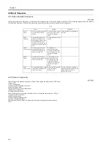
The operation sequence of this printer is controller by the microprocessor (CPU) on the engine controller PCB. The following diagram shows the purposes
of each periods from power ON until the main motor stops after the completion of printing. See the timing chart.
T-2-1
2.2.2 Power-on sequence
0007-9887
The following is the sequence from power ON until the engine controller enters STBY mode.
1) Power ON
2) CPU initialization
3) Video interface communication start
4) Residual paper check
Checks the sensors for any residual paper.
5) Main motor initial drive
6) Fixing heater initial drive
Drive the fixing heater so that the fixing unit reaches its targeted temperature of 100 deg C.
7) Scanner motor initial drive
8) High-voltage control
Clean the transfer sharging roller.
9) Failure/ abnormality check
Detects scanner failure, fixing unit failure and door open during the periods mentioned
above.
Period
Purpose
Remarks
WAIT
(Wait)
From power-ON until the end
of the main motor initial
rotation.
To clean the drum surface
of potential and to clean
the transfer charging
roller.
Toner cartridge in/out detection is
executed.
STBY
(Standby)
From the end of the WAIT
period or the LSTR period
until the input of the pick-up
command from the video
controller. Or, from the end of
the LSTR period until power-
OFF.
To keep the printer ready
to print.
INTR
(Initial rotation)
From the input of the print
command from the video
controller until the pick up
solenoid is turned ON
To stabilize the
photosensiteive drum
sensitivity in preparation
for printing,Also to clean
the transfer charging
roller.
PRINT
(Print)
From the end of the initial
rotation until the primary high-
voltage is turned OFF.
To form image on the
photosensitive drum
according to the video
signals input from the
interface controller, and
transfers the image to
paper.
LSTR
(Last rotation)
From the primary high-voltage
is turned OFF until the main
motor stops rotating.
Delivers the final page and
cleans the transfer
charging roller.
As soon as the print command is
input from the video controller, the
printer enters the INITIAL
ROTATION period.
Содержание LBP-3000
Страница 1: ...H T T P W W W F I X C L U B C O M C N Mar 10 2005 Service Manual LBP3000 2900 Series LBP2900 ...
Страница 2: ...H T T P W W W F I X C L U B C O M C N ...
Страница 6: ...H T T P W W W F I X C L U B C O M C N ...
Страница 12: ...H T T P W W W F I X C L U B C O M C N Contents ...
Страница 13: ...H T T P W W W F I X C L U B C O M C N Chapter 1 PRODUCT DESCRIPTION ...
Страница 14: ...H T T P W W W F I X C L U B C O M C N ...
Страница 16: ...H T T P W W W F I X C L U B C O M C N ...
Страница 23: ...H T T P W W W F I X C L U B C O M C N Chapter 2 TECHNICAL REFERENCE ...
Страница 24: ...H T T P W W W F I X C L U B C O M C N ...
Страница 44: ...H T T P W W W F I X C L U B C O M C N Chapter 2 2 18 ...
Страница 51: ...H T T P W W W F I X C L U B C O M C N Chapter 3 DISASSEMBLY AND ASSEMBLY ...
Страница 52: ...H T T P W W W F I X C L U B C O M C N ...
Страница 87: ...H T T P W W W F I X C L U B C O M C N Chapter 3 3 33 F 3 161 ...
Страница 88: ...H T T P W W W F I X C L U B C O M C N ...
Страница 89: ...H T T P W W W F I X C L U B C O M C N Chapter 4 MAINTENANCE AND INSPECTION ...
Страница 90: ...H T T P W W W F I X C L U B C O M C N ...
Страница 92: ...H T T P W W W F I X C L U B C O M C N ...
Страница 98: ...H T T P W W W F I X C L U B C O M C N ...
Страница 99: ...H T T P W W W F I X C L U B C O M C N Chapter 5 TROUBLESHOOTING ...
Страница 100: ...H T T P W W W F I X C L U B C O M C N ...
Страница 102: ...H T T P W W W F I X C L U B C O M C N ...
Страница 107: ...H T T P W W W F I X C L U B C O M C N Chapter 6 APPENDIX ...
Страница 108: ...H T T P W W W F I X C L U B C O M C N ...
Страница 110: ...H T T P W W W F I X C L U B C O M C N ...
Страница 117: ...H T T P W W W F I X C L U B C O M C N Mar 10 2005 ...
Страница 118: ...H T T P W W W F I X C L U B C O M C N ...


