


Chapter 4
4-16
4.3.5 Drive Unit
0020-5659
iPF810 / iPF820
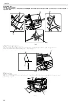
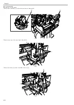
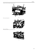
a) Feed motor
Removing the feed motor
1) To remove feed motor [1], loosen four screws [2] and remove timing belt [3] and spring [4].
2) Remove four loosened screws [2] to release feed motor [1] and remove the connector.
Reinstalling the feed motor
To reassemble the feed roller drive timing belt [3] into position, set the tension of timing belt [3] by adjusting the pressure of spring [4]. Then, fix feed motor [1].
F-4-33
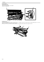
b) Action to take after replacing the feed roller encoder and feed roller
This printer as shipped has the feed roller eccentricity (that is, variations in the rate of paper feed from rotation to rotation) corrected for enhanced media feed ac-
curacy. When the feed roller HP sensor or feed roller encoder and feed roller pertaining to the correction of eccentricity variations has been replaced, therefore,
they should require adjustment.
Execute service mode under the following conditions to launch automatic adjustment:
Service mode: SERVICE MODE > ADJUST > PRINT PATTERN > LF TUNING
Media type: Glossy photo paper
If adjustment cannot be done properly by selecting "SERVICE MODE > ADJUST > PRINT PATTERN > LF TUNING" (auto adjustment), carry out manual ad-
justment.
Service mode SERVICE MODE > ADJUST > PRINT PATTERN > LF TUNING2
Media type: Gloss photo paper
Check the printed pattern and enter values for adjustment.
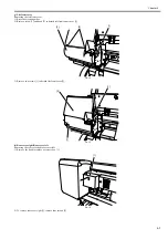
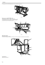
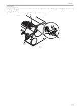
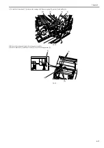
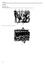
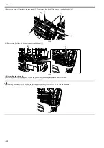
c) Carriage motor
Removing the carriage motor
1) Move the carriage onto the platen. "See Disassembly/Reassembly > Disassembly/Reassembly Precautions > Opening the Cap and Moving the Wiper Unit."
2) Remove two screws [1] and connector [2] to remove carriage HP sensor assembly [3].
F-4-34
[2]
[3]
[1]
[2]
[4]
[2]
[3]
[1]
[2]
Содержание iPF800 Series
Страница 1: ...Aug 13 2008 Service Manual iPF800 series ...
Страница 2: ......
Страница 6: ......
Страница 11: ...Chapter 1 PRODUCT DESCRIPTION ...
Страница 12: ......
Страница 14: ......
Страница 38: ...Chapter 1 1 24 Hold this lever to pull out the lower roll unit ...
Страница 90: ...Chapter 1 1 76 3 Push in the left and right Basket Rods toward the back all the way until they stop F 1 41 ...
Страница 100: ...Chapter 1 1 86 ...
Страница 101: ...Chapter 2 TECHNICAL REFERENCE ...
Страница 102: ......
Страница 147: ...Chapter 2 2 43 This function relays the image data from the main controller PCB to the printhead ...
Страница 158: ......
Страница 159: ...Chapter 3 INSTALLATION ...
Страница 160: ......
Страница 162: ......
Страница 176: ...Chapter 3 3 14 ...
Страница 177: ...Chapter 4 DISASSEMBLY REASSEMBLY ...
Страница 178: ......
Страница 180: ......
Страница 227: ...Chapter 4 4 47 Media type Gloss photo paper 2 Paper gap adjustment Service mode SERVICE MODE ADJUST GAP CALIB ...
Страница 238: ...Chapter 4 4 58 ...
Страница 239: ...Chapter 5 MAINTENANCE ...
Страница 240: ......
Страница 242: ......
Страница 246: ...Chapter 5 5 4 5 Close upper cover 1 F 5 6 1 ...
Страница 247: ...Chapter 5 5 5 ...
Страница 248: ......
Страница 249: ...Chapter 6 TROUBLESHOOTING ...
Страница 250: ......
Страница 252: ......
Страница 274: ......
Страница 275: ...Chapter 7 SERVICE MODE ...
Страница 276: ......
Страница 278: ......
Страница 301: ......
Страница 302: ......
Страница 303: ...Chapter 8 ERROR CODE ...
Страница 304: ......
Страница 306: ......
Страница 318: ...Chapter 8 8 12 ...
Страница 319: ...Aug 13 2008 ...
Страница 320: ......


